Nissan Murano: Back Door / Back Door Striker
REMOVAL
Remove back door kicking plate. Refer to Removal and Installation.
Remove bolts and back door striker.
INSTALLATION
Installation is in the reverse order of removal.
CAUTION:
-
Do not reuse back door striker bolts.
-
Tighten bolts to specification. Refer to Exploded View.
-
After installation, check back door open/close operation. If necessary, adjust door striker. Refer to Adjustment.
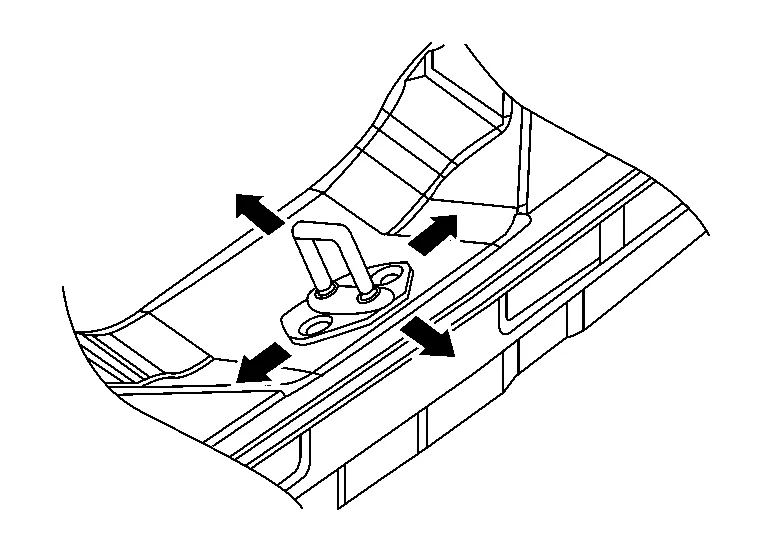
DOOR STRIKER ADJUSTMENT
Loosen door striker bolts.
Adjust door striker so that it becomes parallel with front door lock insertion direction.
CAUTION:
Perform calibration of automatic back door position information. Refer to Description.
Tighten door striker bolts to specification. Refer to Exploded View.
 Back Door Assembly
Exploded View
1.
Back door
2.
Back door weather stripping
3.
Back door hinge (LH/RH)
4.
Back door upper stud ball or spindle unit upper hinge (with power back door) (LH)
5...
 Back Door Hinge
Removal and Installation
REMOVALRemove back door assembly. Refer to Removal and Installation.
Partially remove rear of headlining. Refer to Removal and Installation...
Other information:
Nissan Murano (Z52) 2015-2024 Service Manual: Power Supply and Ground Circuit. Av Control Unit
Diagnosis Procedure CHECK FUSE Check that the following fuses are not blown: Terminal No. Signal name Fuse No. Capacity 7 ACC power supply 7 10 A 17 Ignition power supply 29 10 A 19 Battery power supply 15 20 A Are the fuses blown? YES>> Replace the blown fuse after repairing the affected circuit...
Nissan Murano (Z52) 2015-2024 Service Manual: Integrated Homelink Transceiver Does Not Operate
Diagnosis Procedure CHECK INTEGRATED HOMELINK® TRANSCEIVER Check integrated HomeLink® transceiver. Refer to Component Function Check. Is the inspection result normal? YES>> GO TO 2. NO>> Repair or replace the malfunctioning parts. REPLACE AUTO ANTI-DAZZLING INSIDE MIRROR Replace auto anti-dazzling inside mirror...
Categories
- Manuals Home
- Nissan Murano Owners Manual
- Nissan Murano Service Manual
- All-Wheel Drive (AWD) (if so equipped)
- Fuel recommendation
- Tire rotation
- New on site
- Most important about car
Fuel gauge

The gauge indicates the approximate fuel level in the tank.
The gauge may move slightly during braking, turning, acceleration, or going up or down hills.
The gauge needle returns to 0 (Empty) after the ignition switch is placed in the OFF position.