Nissan Murano: Removal and Installation / Air Breather Hose
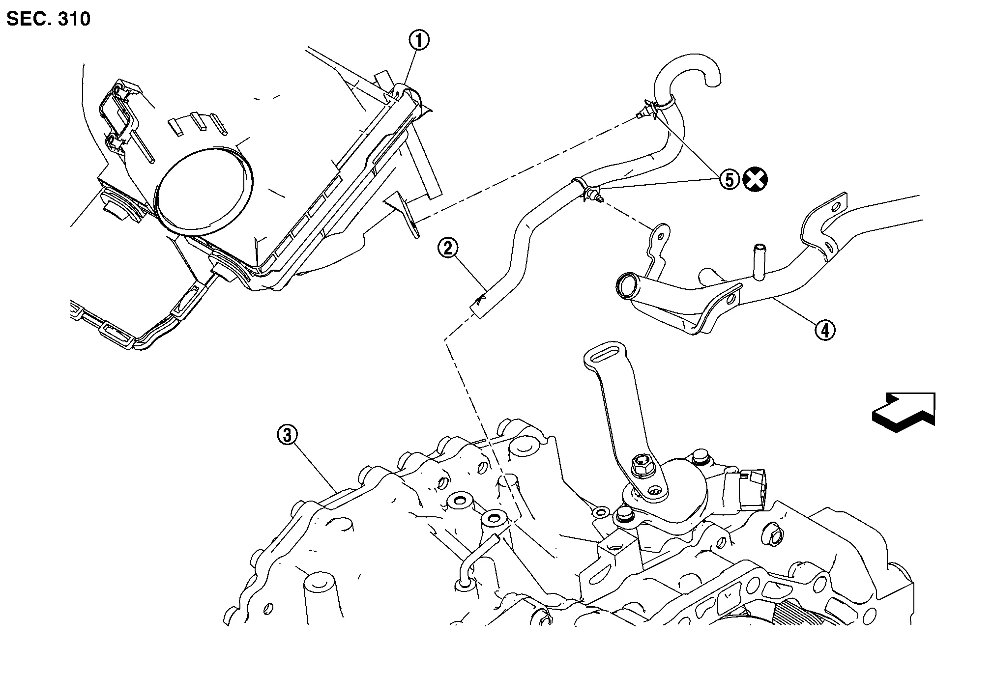
| 1. | Air cleaner case | 2. | Air breather hose | 3. | Transaxle assembly |
| 4. | Heater pipe | 5. | Clip | Front |
REMOVAL
Remove the front air duct, air cleaner cases (upper and lower) with mass air flow sensor and air duct assembly. Refer to Removal and Installation.
Remove air breather hose.
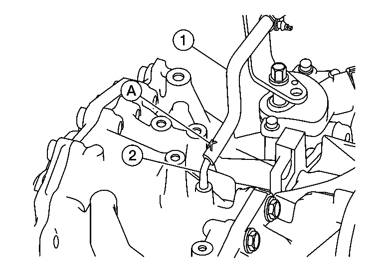
INSTALLATION
Installation is in the reverse order of removal.
CAUTION:
-
Do not reuse clips.
-
Check that air breather hose is not collapsed or blocked due to folding or bending when installed.
-
Insert air breather hose (1) to air breather tube (2) all the way to the curve of the tube.
-
Insert air breather hose to air breather tube so that the paint mark (A) is facing upward.
 Tcm
Tcm
Exploded View
1.
Bracket
2.
TCM
Removal and Installation
CAUTION:
To replace TCM, perform "WRITE IP CHARA – REPLACEMENT TCM" of the CONSULT Work Support before removing TCM and save TCM data in CONSULT...
 Control Valve
Exploded View
1.
Transaxle assembly
2.
Terminal cord assembly
3.
Control valve
4.
Bracket
5.
O-ring
6.
Oil strainer assembly
7...
Other information:
Nissan Murano (Z52) 2015-2024 Service Manual: Open/closure Function
Diagnosis Procedure Back door auto closure function does not operate when back door opening and closing operations are performed.CHECK DTC WITH AUTOMATIC BACK DOOR CONTROL MODULE Check that DTC is not detected with automatic back door control module. Is the inspection result normal? YES>> GO TO 2...
Nissan Murano (Z52) 2015-2024 Service Manual: C1205 4wd Actuator Relay
DTC Description DTC DETECTION LOGICMalfunction has been detected from AWD actuator relay integrated with AWD control unit, or malfunction related to AWD solenoid has been detected. DTC No. CONSULT screen terms (Trouble diagnosis content) DTC detecting condition C1205 4WD ACTUATOR RLY (4WD actuator relay) Diagnosis condition Ignition switch: ON Signal — Threshold — Diagnosis delay time — POSSIBLE CAUSE Internal malfunction of AWD control unit Malfunction of AWD solenoid power supply circuit (ground short) FAIL-SAFEFront-wheel drive or shifts to 4-wheel drive (rear-wheels still have some driving torque)...
Categories
- Manuals Home
- Nissan Murano Owners Manual
- Nissan Murano Service Manual
- Turning the AEB system on/off
- Shift lock release
- Passenger compartment
- New on site
- Most important about car
Driver and passenger supplemental knee air bag

Driver’s side
The knee air bag is located in the knee bolster, on the driver’s and passenger’s side. All of the information, cautions and warnings in this manual apply and must be followed. The knee air bag is designed to inflate in higher severity frontal collisions, although it may inflate if the forces in another type of collision are similar to those of a higher severity frontal impact. It may not inflate in certain collisions.

Passenger’s side