Nissan Murano: Removal and Installation / Control Valve
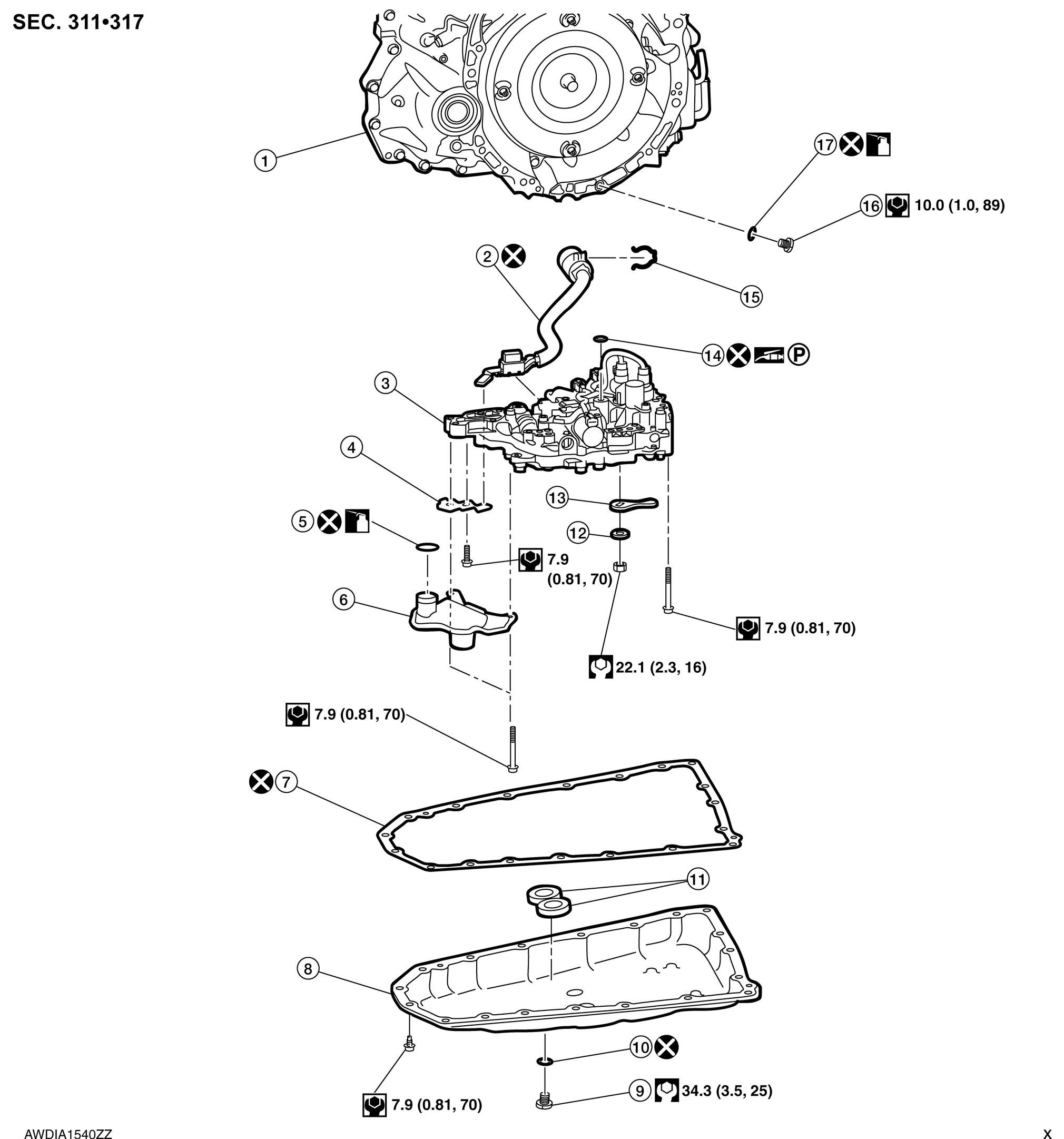
| 1. | Transaxle assembly | 2. | Terminal cord assembly | 3. | Control valve |
| 4. | Bracket | 5. | O-ring | 6. | Oil strainer assembly |
| 7. | Oil pan gasket | 8. | Oil pan | 9. | Drain plug |
| 10. | Drain plug gasket | 11. | Magnet | 12. | Spring washer |
| 13. | Manual plate | 14. | Lip seal | 15. | Snap ring |
| 16. | Overflow plug | 17. | O-ring | ||
 |
: Always replace after every disassembly. | ||||
 |
: N·m (kg-m, ft-lb) | ||||
 |
: N·m (kg-m, in-lb) | ||||
 |
: Apply petroleum jelly | ||||
 |
: Apply CVT fluid | ||||
CAUTION:
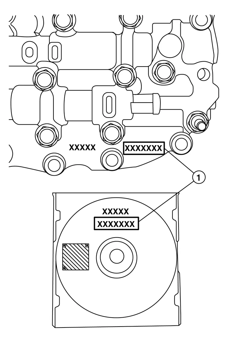
Perform the following items when replacing the control valve.
-
Check that the part number and serial number of the new control valve (1) are identical to those of the attached CD (1).
-
If old QR code sticker is affixed to transmission range switch, remove the QR code sticker and affix new QR code sticker included with new control valve.
 NOTE:
NOTE:
The CD provided with the new control valve contains important calibration data that must be installed with CONSULT after installation of the new control valve. Do not discard the CD.
REMOVAL
Disconnect battery negative terminal. Refer to Removal and Installation.
Remove drain plug from oil pan and then drain the CVT fluid.
Remove drain plug gasket.
CAUTION:
Do not reuse drain plug gasket.
Remove the oil pan bolts, and then remove the oil pan and oil pan gasket.
CAUTION:
Do not reuse oil pan gasket.
Remove the magnets from the oil pan.
NOTE:
Be sure to note the location of the magnets in the oil pan before removal.
Remove the lock nut (1), spring washer (2), and manual plate (3) from manual shaft (A).
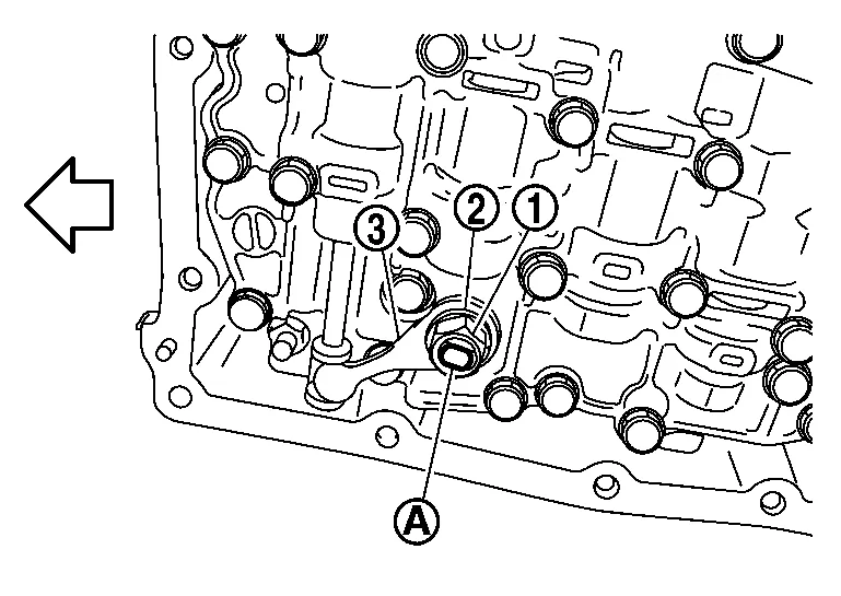
| : Front |
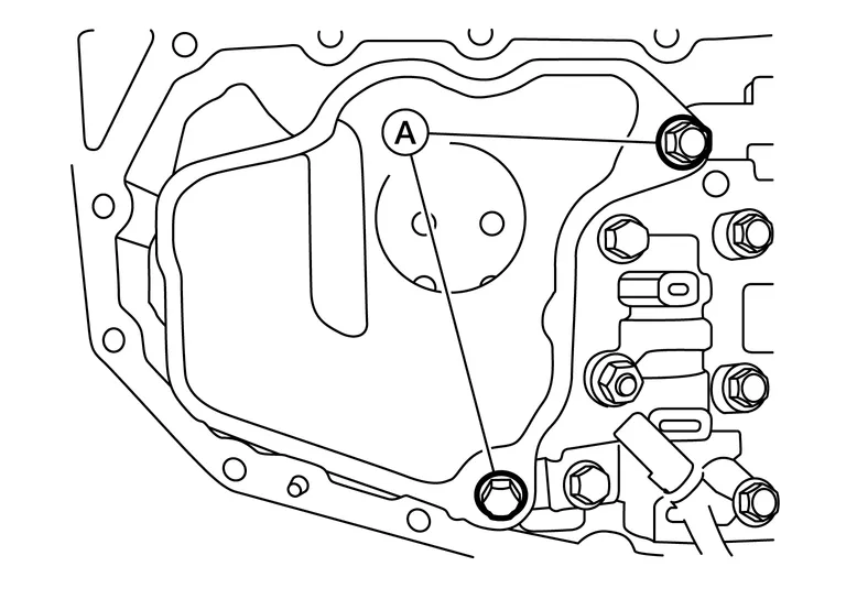
Remove the oil strainer assembly bolts (A) and remove the oil strainer assembly.
Remove CVT fluid temperature sensor bracket (1).
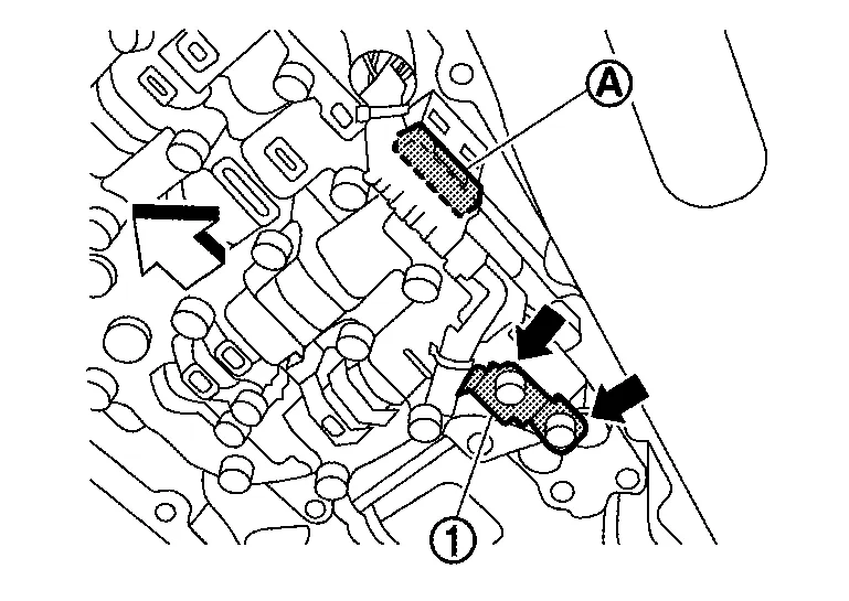
 |
: Bolt |
| : Front |
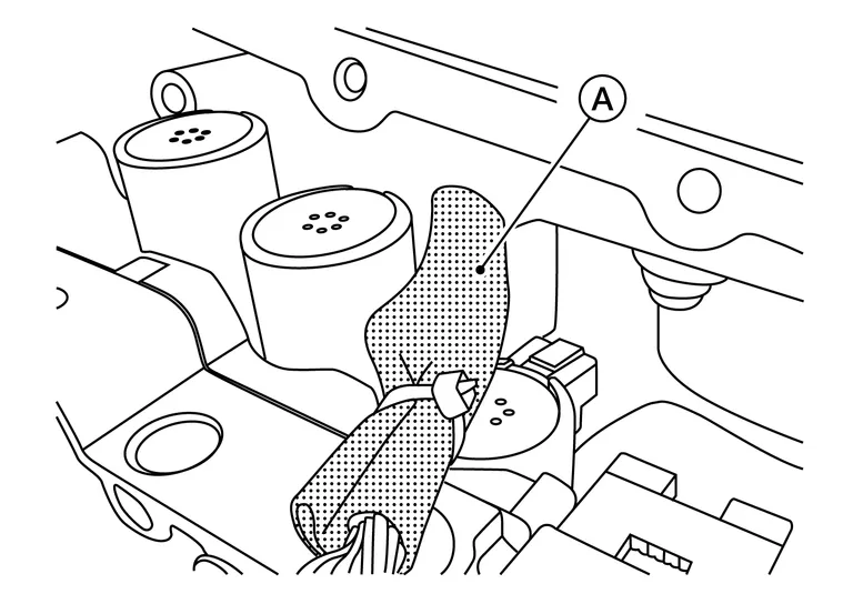
Disconnect control valve harness connector (A).
Remove the control valve bolts (A) and (B), and then remove the control valve from the transaxle case.
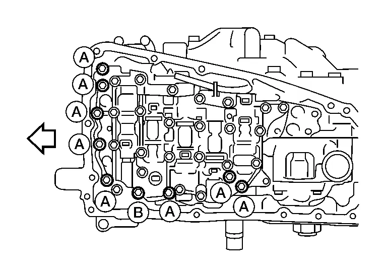
| : Front |
CAUTION:
Do not drop the control valve, ratio control valve and manual shaft.
NOTE:
Control valve bolt heads may be marked with a number "7". Bolts marked as "7" are the bolts that need to be removed in order to remove the control valve.
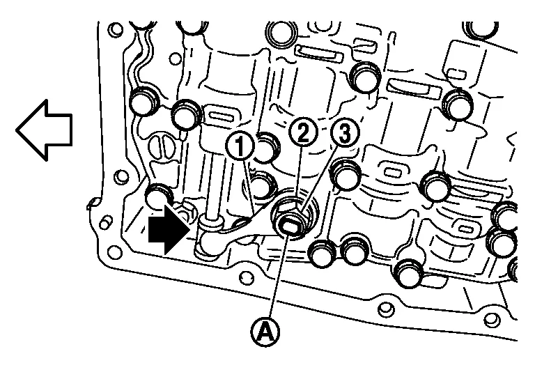
Remove the lip seal (1) from the transaxle case.
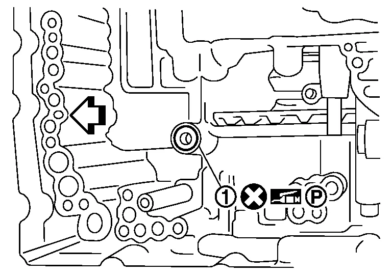
CAUTION:
Do not reuse lip seal.
| : Front |
INSTALLATION
Install the lip seal (1) to the transaxle case.
CAUTION:
-
Do not reuse lip seal.
-
Apply petroleum jelly to lip seal.
| : Front |
Install the control valve to the transaxle case.
CAUTION:
-
Do not drop the control valve, ratio control valve and manual shaft.
-
Ensure the harness (A) is correctly routed and does not get pinched.
Secure the control valve using bolts (A), (B) and (C).
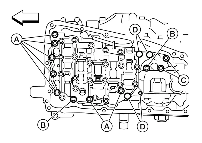
CAUTION:
Ensure the harness is correctly routed and does not get pinched.
NOTE:
-
Leave bolt holes (D) blank at this step.
-
Install bolts (C) without the strainer bracket.
| Bolt | Bolt length mm (in) | Number of bolts |
|---|---|---|
| A | 54 (2.13) | 7 |
| B | 44 (1.73) | 2 |
| C | 25 (0.98) | 2 |
| : Front |
Connect the control valve harness connector (A).
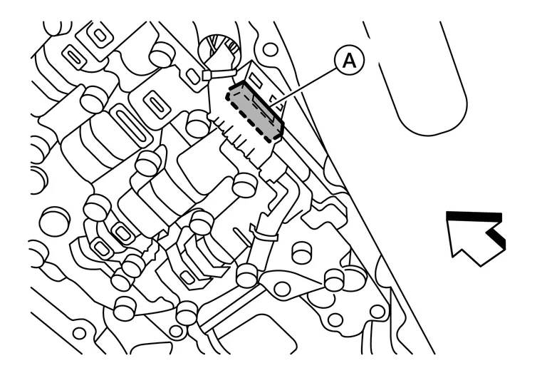
| : Front |
CAUTION:
Securely insert the harness connector until it clicks and locks.
Install the CVT fluid temperature sensor bracket to the valve body with bolt (A).
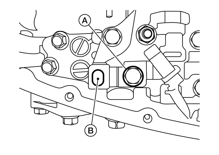
NOTE:
Leave bolt hole (B) blank as it will be used to secure the oil strainer at a later step.
| Bolt | Bolt length mm (in) | Number of bolts |
|---|---|---|
| A | 54 (2.13) | 1 |
Install new O-ring to oil strainer assembly.
CAUTION:
-
Do not reuse O-ring.
-
Apply CVT fluid to O-ring.
NOTE:
New oil strainers come with a new O-ring already installed.
Install new oil strainer with bolts (A).
| Bolt | Bolt length mm (in) | Number of bolts |
|---|---|---|
| A | 54 (2.13) | 2 |
Install the manual plate (1) while aligning the ends as shown.
-
Align the slot of the manual plate with the manual shaft (A).
-
Align the end of the manual plate with the cutout of the manual valve.
CAUTION:
Install the end of the manual plate into the cutout of the manual valve.
|
: Cutout |
| : Front |
Install the spring washer (2) and the lock-nut (3), and then tighten to the specified torque.
Install the magnets in the oil pan in their original location.
CAUTION:
Completely clean the iron powder from the magnet area of oil pan and the magnet.
Install the oil pan to the transaxle case with the following procedure.Install the oil pan gasket to the oil pan.
CAUTION:
-
Completely wipe out any moisture, oil, and old gasket from the oil pan gasket surface and bolt hole of oil pan and transaxle case.
-
Do not reuse oil pan gasket.
| : Front |
Install drain plug gasket to drain plug.
CAUTION:
Do not reuse drain plug gasket.
Install drain plug to oil pan.
Install new QR code sticker (1) on Transmission Range (inhibitor) switch (2).
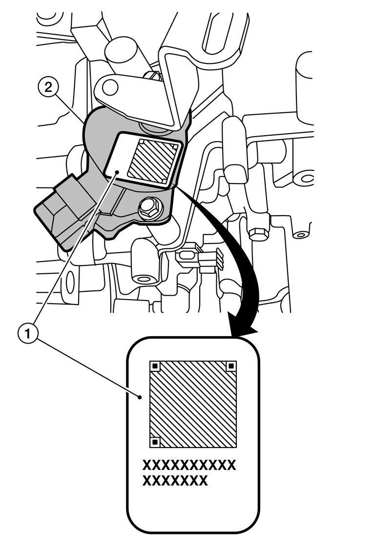
NOTE:
If sticker is not included with parts, contact Powertrain Call Center to report.
Flush the CVT fluid cooler and lines. Refer to CVT Fluid Cooler Flush.
Connect battery negative terminal. Refer to Removal and Installation.
Fill the transaxle assembly with CVT fluid. Refer to Refilling.
NOTE:
Perform "ADDITIONAL SERVICE WHEN REPLACING CONTROL VALVE." Refer to Description.
INSPECTION AFTER REMOVAL
Check oil pan for foreign material.
If a large amount of worn material is found, clutch plate may be worn.
If iron powder is found, bearings, gears, or clutch plates may be worn.
If aluminum powder is found, bushing may be worn, or chips or burrs of aluminum casting parts may enter.
Check points where wear is found in all cases.
INSPECTION AFTER INSTALLATION
Check the CVT fluid level and leakage. Refer to Inspection.
ADJUSTMENT AFTER INSTALLATION
Perform "ADDITIONAL SERVICE WHEN REPLACING CONTROL VALVE." Refer to Description.
 Air Breather Hose
Exploded View
1.
Air cleaner case
2.
Air breather hose
3.
Transaxle assembly
4.
Heater pipe
5.
Clip
Front
Removal and Installation
REMOVALRemove the front air duct, air cleaner cases (upper and lower) with mass air flow sensor and air duct assembly...
 Input Speed Sensor
Exploded View
1.
Input speed sensor
2.
O-ring
3.
Transaxle assembly
: Apply CVT fluid
Removal and Installation
REMOVALRemove the battery tray...
Other information:
Nissan Murano (Z52) 2015-2024 Owners Manual: Towing safety
Your vehicle may be equipped with an optional trailer tow package. The trailer tow package includes a receiver-type frame mounted hitch. This hitch is rated for the maximum towing capacity of this vehicle when the proper towing equipment is used...
Nissan Murano (Z52) 2015-2024 Service Manual: Center Console Assembly
Exploded View 1. Center console side finisher (RH) 2. Center console side finisher (LH) 3. Center console lower side finisher (LH) 4. Center console reinforcement bracket 5. Mood lamp [front console LH (if equipped)] 6. Mood lamp lens [front console LH (if equipped)] 7...
Categories
- Manuals Home
- Nissan Murano Owners Manual
- Nissan Murano Service Manual
- Turning the AEB system on/off
- Fuel recommendation
- Settings
- New on site
- Most important about car
Vehicle security system

Your vehicle has two types of security systems:
Vehicle security system NISSAN Vehicle Immobilizer SystemThe vehicle security system provides visual and audible alarm signals if someone opens the doors, liftgate or the hood when the system is armed. It is not, however, a motion detection type system that activates when a vehicle is moved or when a vibration occurs.