Nissan Murano: Removal and Installation / Air Breather
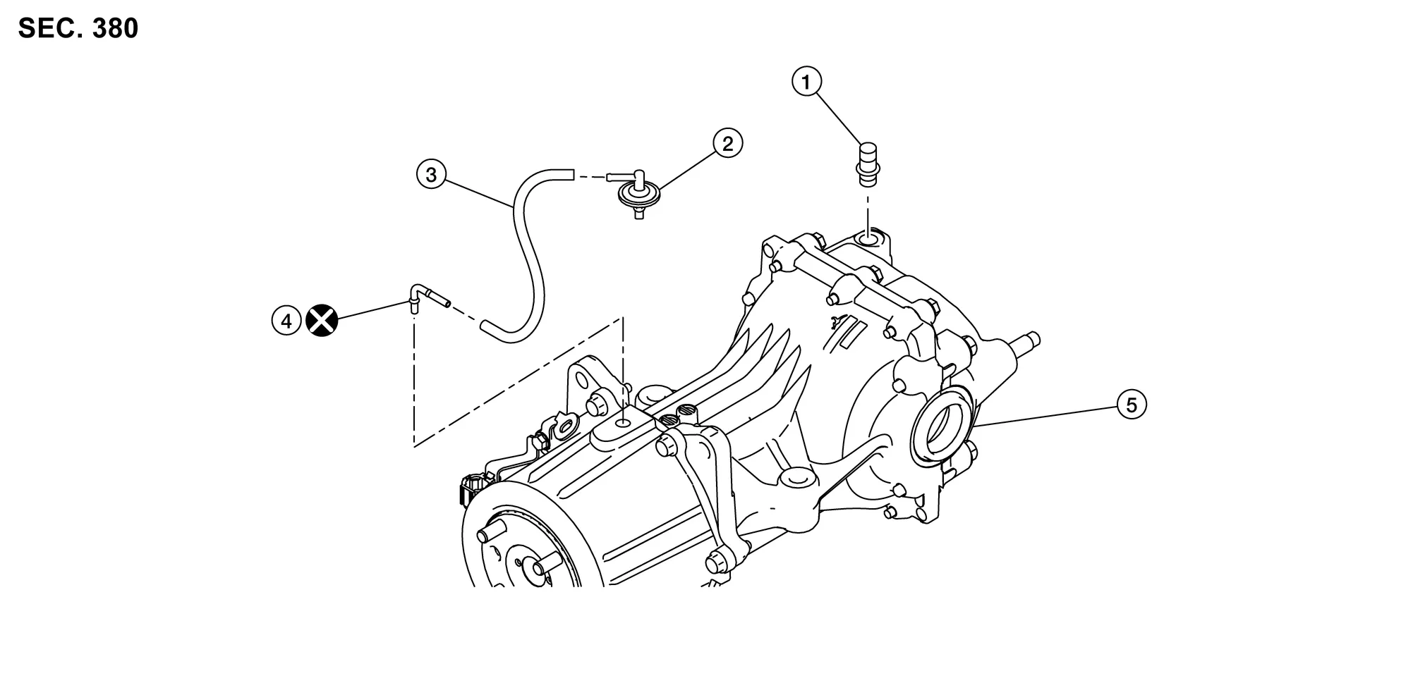
| 1. | Rear final drive breather | 2. | Breather connector (resin) | 3. | Air breather hose |
| 4. | Breather connector (metal) | 5. | Rear final drive assembly | ||
 : Always replace after every disassembly. : Always replace after every disassembly. |
|||||
REMOVAL
Final Drive Side
Remove rear final drive. Refer to Removal and Installation.
Using a suitable tool remove rear final drive breather.
CAUTION:
Do not damage rear final drive breather or rear final drive during removal of rear final drive breather.
Electric Controlled Coupling Side
Remove air breather hose assembly from breather connector (metal) on electric controlled coupling assembly.
Remove breather connector (resin) (1) together with air breather hose (3) from rear suspension member.

Remove breather connector (metal) (2) from electric controlled coupling assembly.
-
When removing/installing breather connector (metal) (2), remove electric controlled coupling assembly from rear final drive assembly. Refer to Removal and Installation.
CAUTION:
Do not reuse breather connector (metal).
INSTALLATION
Final Drive Side
Installation is in the reverse order of removal.
CAUTION:
Do not damage rear final drive breather or rear final drive during removal of rear final drive breather.
Electric Controlled Coupling Side
Installation is in the reverse order of removal.
-
When installing air breather hose, make sure there are no pinched or restricted areas on air breather hose caused by bending or winding.
-
Securely install breather connector (metal) to the electric controlled coupling assembly with the tip of tube faced in the Nissan Murano vehicle front direction. In addition, insert air breather hose (1) to tube spool part (A) of breather connector (metal) (2).

CAUTION:
Do not reuse breather connector (metal).

: Front -
Install breather connector (resin) (1), air breather hose (2), hose connector (3), and clip (4) based on hose paint mark (A) as shown in the figure, complying with the directions below.

CAUTION:
-
Do not reuse breather connector (metal).
-
Be careful with insert dimension of breather connector (resin) and hose connector, and set position of clip.
Insert dimension of breather connector (resin) and hose connector : 15 mm (0.59 in) from breather connector end (air breather hose side) and hose connector end (air breather hose side) Set position of clip : 5 mm (0.20 in) from breather hose end -
Cut extra band of clip.
-
 Electric Controlled Coupling
Exploded View
Rear final drive assembly
Wave spring
Electric controlled coupling assembly
Reamer bolt
Connector bracket
Stud bolt
: N·m (kg-m, in-lb)
: N·m (kg-m, ft-lb)
: Always replace after every disassembly...
 Unit Removal and Installation. Rear Final Drive Assembly
Exploded View
1.
Final drive bracket
2.
Stopper
3.
Rear final drive assembly
Removal and Installation
NOTE:
When removing components such as hoses, tubes/lines, etc...
Other information:
Nissan Murano (Z52) 2015-2024 Service Manual: Automatic Back Door Warning Does Not Operate. Buzzer
Diagnosis Procedure Automatic back door warning buzzer does not operate when automatic back door warning function is performed.CHECK DTC WITH AUTOMATIC BACK DOOR CONTROL MODULE Check that DTC is not detected with automatic back door control module. Is the inspection result normal? YES>> GO TO 2...
Nissan Murano (Z52) 2015-2024 Owners Manual: Heating (A/C OFF)
The air conditioner does not activate.When you need to heat only, use this mode. Press the AUTO button. Turn the temperature control dial to set the desired temperature. The temperature of the passenger compartment will be maintained automatically...
Categories
- Manuals Home
- Nissan Murano Owners Manual
- Nissan Murano Service Manual
- Fuel recommendation
- Indicator lights
- Vehicle Dynamic Control (VDC) OFF switch
- New on site
- Most important about car
LATCH (Lower Anchors and Tethers for CHildren) system

LATCH system lower anchor locations - bench seat
Your vehicle is equipped with special anchor points that are used with LATCH system compatible child restraints. This system may also be referred to as the ISOFIX or ISOFIX compatible system. With this system, you do not have to use a vehicle seat belt to secure the child restraint unless the combined weight of the child and child restraint exceeds 65 lbs. (29.5 kg). If the combined weight of the child and child restraint is greater than 65 lbs. (29.5 kg), use the vehicle’s seat belt (not the lower anchors) to install the child restraint. Be sure to follow the child restraint manufacturer’s instructions for installation.