Nissan Murano: Wiper & Washer :: Removal and Installation / Washer Tank
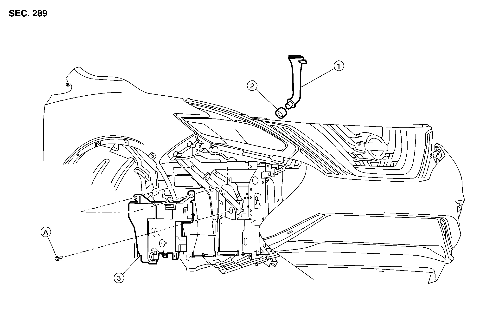
| 1. | Washer tank inlet | 2. | Seal | 3. | Washer tank |
| A. | Refer to Installation. |
REMOVAL
Remove the front combination lamp (RH). Refer to Removal and Installation.
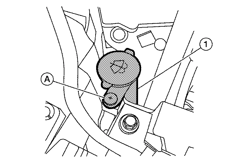
Using a suitable tool, remove clip (A) from the radiator core support and remove the washer tank inlet (1) from the washer tank.
Disconnect harness connector from the front and rear washer motor.
Disconnect harness connector from the washer fluid level switch.
Release the harness from the washer tank.
Disconnect the front and rear washer tubes from the front and rear washer motor.
Remove the washer tank bolts and washer tank.
INSTALLATION
Installation is in the reverse order of removal.
CAUTION:
-
Add water up to the top of washer tank inlet after installing. Check that no leaks exist.
-
Fill washer tank with specified amount of fluid. Refer to Specifications.
-
Tighten the washer tank bolts to specification in the sequence shown.
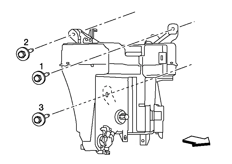
 : Front
| Washer tank bolts | : 4.5 N·m (0.46 kg-m, 40 in-lb) |

 Front and Rear Washer Motor
Exploded View
1.
Washer tank
2.
Front and rear washer motor
3.
Washer fluid level switch
Removal and Installation
REMOVALRemove the front fender protector (RH)...
Other information:
Nissan Murano (Z52) 2015-2024 Service Manual: Electric Resistance Spot Welding
Principles of Spot Welding Resistance spot welding is a kind of electric resistance welding. It is classified as pressure welding. Two or three sheets of metal are overlapped and pressed, and current is passed through the mating surfaces. As the current flows, the metals melt due to Joule heat at the mating surfaces and are joined by the pressure...
Nissan Murano (Z52) 2015-2024 Service Manual: Tcm
Exploded View 1. Bracket 2. TCM Removal and Installation CAUTION: To replace TCM, perform "WRITE IP CHARA – REPLACEMENT TCM" of the CONSULT Work Support before removing TCM and save TCM data in CONSULT. Refer to Description...
Categories
- Manuals Home
- Nissan Murano Owners Manual
- Nissan Murano Service Manual
- Tire rotation
- Memory storage function (key-link)
- Vehicle Dynamic Control (VDC) OFF switch
- New on site
- Most important about car
Luggage hooks

When securing items using luggage hooks located on the back of the seat or side finisher do not apply a load over more than 6.5 lbs. (29 N) to a single hook.
The luggage hooks that are located on the floor should have loads less than 110 lbs. (490 N) to a single hook.