
Nissan Murano: Dtc/circuit Diagnosis / U1232 Steering Angle Sensor
DTC DETECTION LOGIC
| DTC No. |
CONSULT screen terms (Trouble diagnosis content) | DTC detection condition | |
|---|---|---|---|
| U1232 |
ST ANGLE SEN CALIB (Steering angle sensor calibration) |
Diagnosis condition | When ignition switch is ON |
| Signal (terminal) | — | ||
| Threshold | — | ||
| Diagnosis delay time | — | ||
POSSIBLE CAUSE
-
Neutral position adjustment of the steering angle sensor is incomplete
-
Steering angle sensor
FAIL-SAFE
Predictive course line is not displayed
PERFORM DTC CONFIRMATION PROCEDURE
 CONSULT
-
Ignition switch ON.
-
Select “Self diagnostic result” mode of “AVM”.
-
Check DTC.
Is DTC U1232 detected?
YES>>Proceed to DTC Diagnosis Procedure.
NO>>To check malfunction symptom before repair: Refer to Intermittent Incident.
NO>>Confirmation after repair: Inspection End.
ADJUST THE PREDICTIVE COURSE LINE CENTER POSITION OF THE STEERING ANGLE SENSOR
Adjust the steering angle sensor neutral position on ABS actuator and electrical unit (control unit) side. Refer to Work Procedure or Work Procedure.
 NOTE:
NOTE:
When DTC U1232 is detected, adjust the predictive course line center position of the steering angle sensor.
>>
GO TO 2.
PERFORM DTC CONFIRMATION PROCEDURE
CONSULT
-
Ignition switch ON.
-
Erase DTC.
-
Select “Self diagnostic result” mode of “AVM”.
-
Check DTC.
Is DTC U1232 detected?
YES>>Replace steering angle sensor. Refer to Removal and Installation or Removal and Installation.
NO>>Inspection End.
 U111a Rear Camera Image Signal Circuit
DTC Description
DTC DETECTION LOGIC DTC No.
CONSULT screen terms
(Trouble diagnosis content) DTC detection condition
U111A
REAR CAMERA IMAGE SIGNAL
(CAN COMM CIRCUIT)
Diagnosis condition
When ignition switch is ON
Signal (terminal)
Rear camera image signal (terminal 20)
Threshold
Rear camera image signal circuit is shorted or open
Diagnosis delay time
—
POSSIBLE CAUSE
Rear camera image signal circuit
Around view monitor control unit
Rear camera
FAIL-SAFECamera image is not displayed (gray screen display)
DTC Confirmation Procedure
PERFORM DTC CONFIRMATION PROCEDURE
CONSULT
Ignition switch ON...
 U1302 Camera Power Volt
DTC Description
DTC DETECTION LOGIC DTC No.
CONSULT screen terms
(Trouble diagnosis content) DTC detection condition
U1302
CAMERA POWER VOLT
(Camera power voltage)
Diagnosis condition
When ignition switch is ON
Signal (terminal)
Camera power supply circuits
Threshold
Camera power supply voltage is 5...
Other information:
Nissan Murano (Z52) 2015-2024 Service Manual: U111a Rear Camera Image Signal Circuit
DTC Description DTC DETECTION LOGIC DTC No. CONSULT screen terms (Trouble diagnosis content) DTC detection condition U111A REAR CAMERA IMAGE SIGNAL (CAN COMM CIRCUIT) Diagnosis condition When ignition switch is ON Signal (terminal) Rear camera image signal (terminal 20) Threshold Rear camera image signal circuit is shorted or open Diagnosis delay time — POSSIBLE CAUSE Rear camera image signal circuit Around view monitor control unit Rear camera FAIL-SAFECamera image is not displayed (gray screen display) DTC Confirmation Procedure PERFORM DTC CONFIRMATION PROCEDURE CONSULT Ignition switch ON...
Nissan Murano (Z52) 2015-2024 Service Manual: Condenser Pipe Assembly
Removal and Installation REMOVALDischarge the refrigerant. Refer to Recycle Refrigerant. Remove the core support cover. Refer to Exploded View. Remove the front grille. Refer to Removal and Installation. Remove the bolt that retains the condenser pipe assembly to the condenser...
Categories
- Manuals Home
- Nissan Murano Owners Manual
- Nissan Murano Service Manual
- Tire rotation
- High Beam Assist (if so equipped)
- Fuel recommendation
- New on site
- Most important about car
Unfastening the seat belts. Checking seat belt operation
Unfastening the seat belts
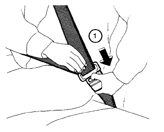
To unfasten the seat belt, press the button
on the buckle  . The seat belt
automatically
retracts.
. The seat belt
automatically
retracts.
