Nissan Murano: Dtc/circuit Diagnosis / U111a Rear Camera Image Signal Circuit
DTC DETECTION LOGIC
| DTC No. |
CONSULT screen terms (Trouble diagnosis content) | DTC detection condition | |
|---|---|---|---|
| U111A |
REAR CAMERA IMAGE SIGNAL (CAN COMM CIRCUIT) |
Diagnosis condition | When ignition switch is ON |
| Signal (terminal) | Rear camera image signal (terminal 20) | ||
| Threshold | Rear camera image signal circuit is shorted or open | ||
| Diagnosis delay time | — | ||
POSSIBLE CAUSE
-
Rear camera image signal circuit
-
Around view monitor control unit
-
Rear camera
FAIL-SAFE
Camera image is not displayed (gray screen display)
PERFORM DTC CONFIRMATION PROCEDURE
 CONSULT
-
Ignition switch ON.
-
Select “Self Diagnostic Result” mode of “AVM”.
-
Check DTC.
Is DTC U111A detected?
YES>>Proceed to DTC Diagnosis Procedure.
NO>>To check malfunction symptom before repair: Intermittent Incident.
NO>>Confirmation after repair: Inspection End.
CHECK REAR CAMERA POWER SUPPLY AND GROUND CIRCUIT CONTINUITY
-
Ignition switch OFF.
-
Disconnect around view monitor control unit connector and rear camera connector.
-
Check continuity between around view monitor control unit connector and rear camera connector.
Around view monitor control unit Rear camera Continuity Connector Terminals Connector Terminals M96 17 D564 1 Yes 18 2 -
Check continuity between around view monitor control unit connector and ground.
Around view monitor control unit Ground Continuity Connector Terminal M96 18 No
Is the inspection result normal?
YES>>GO TO 2.
NO>>Repair or replace harness or connectors.
CHECK REAR CAMERA POWER SUPPLY VOLTAGE
-
Connect around view monitor control unit connector and rear camera connector.
-
Ignition switch ON.
-
Check voltage between around view monitor control unit connector and ground.
Around view monitor control unit Ground Condition Voltage
(Approx.)Connector Terminal M96 18 — CAMERA switch is ON or selector lever in R (reverse). 6.0 V
Is the inspection result normal?
YES>>GO TO 3.
NO>>Replace around view monitor control unit. Refer to Removal and Installation.
CHECK REAR CAMERA IMAGE SIGNAL AND IMAGE SIGNAL GROUND CIRCUIT CONTINUITY
-
Ignition switch OFF.
-
Disconnect around view monitor control unit connector and rear camera connector.
-
Check continuity between around view monitor control unit connector and rear camera connector.
Around view monitor control unit Rear camera Continuity Connector Terminals Connector Terminals M96 20 D564 4 Yes 19 5 -
Check continuity between around view monitor control unit connector and ground.
Around view monitor control unit Ground Continuity Connector Terminal M96 20 No
Is the inspection result normal?
YES>>GO TO 4.
NO>>Repair or replace harness or connectors.
CHECK REAR CAMERA IMAGE SIGNAL
-
Connect around view monitor control unit connector and rear camera connector.
-
Ignition switch ON.
-
Check signal between the terminals of around view monitor control unit connector.
Around view monitor control unit Condition Reference value Connector (+) (−) Terminal Terminal M96 20 19 CAMERA switch is ON or selector lever in R (reverse). 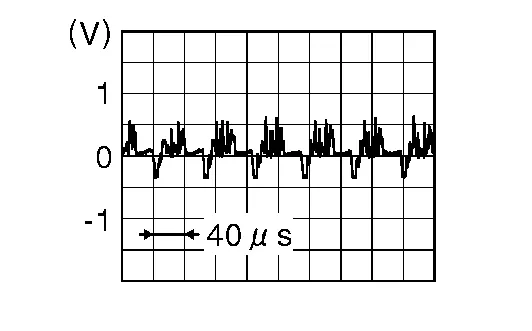
Is the inspection result normal?
YES>>Replace around view monitor control unit. Refer to Removal and Installation.
NO>>Replace rear camera. Refer to Removal and Installation.
 U1010 Control Unit(can)
DTC Description
DTC DETECTION LOGIC DTC No.
CONSULT screen terms
(Trouble diagnosis content) DTC detection condition
U1010
CONTROL UNIT(CAN)
[Control unit(CAN)]
Diagnosis condition
When ignition switch is ON
Signal (terminal)
—
Threshold
—
Diagnosis delay time
—
POSSIBLE CAUSEAround view monitor control unitFAIL-SAFE—
DTC Confirmation Procedure
PERFORM DTC CONFIRMATION PROCEDURE
CONSULT
Ignition switch ON...
 U1232 Steering Angle Sensor
DTC Description
DTC DETECTION LOGIC DTC No.
CONSULT screen terms
(Trouble diagnosis content) DTC detection condition
U1232
ST ANGLE SEN CALIB
(Steering angle sensor calibration)
Diagnosis condition
When ignition switch is ON
Signal (terminal)
—
Threshold
—
Diagnosis delay time
—
POSSIBLE CAUSE
Neutral position adjustment of the steering angle sensor is incomplete
Steering angle sensor
FAIL-SAFEPredictive course line is not displayed
DTC Confirmation Procedure
PERFORM DTC CONFIRMATION PROCEDURE
CONSULT
Ignition switch ON...
Other information:
Nissan Murano (Z52) 2015-2024 Service Manual: Microphone
Removal and Installation REMOVALRemove the map lamp assembly. Refer to Removal and Installation. Remove the microphone connector from the map lamp assembly . Release the microphone pawls, then remove the microphone . : Pawl INSTALLATIONInstallation is in the reverse order of removal...
Nissan Murano (Z52) 2015-2024 Service Manual: Diagnosis and Repair Work Flow
Work Flow DETAILED FLOWINTERVIEW THE CUSTOMER Clarify customer concerns before inspection. First of all, perform an interview utilizing Diagnostic Work Sheet and reproduce the symptom as well as fully understand it. Ask customer about his/her concerns carefully...
Categories
- Manuals Home
- Nissan Murano Owners Manual
- Nissan Murano Service Manual
- System malfunction
- Rear bench seat adjustment
- GAS STATION INFORMATION
- New on site
- Most important about car
Front manual seat adjustment (if so equipped)
Your vehicle seats can be adjusted manually. For additional information about adjusting the seats, refer to the steps outlined in this section.
Forward and backward
