Nissan Murano: Front Suspension :: Removal and Installation / Front Stabilizer

| 1. | Stabilizer | 2. | Front suspension member | 3. | Stabilizer connecting rod |
| 4. | Stabilizer bushing | 5. | Stabilizer clamp |
REMOVAL
Remove front wheels and tires using power tool. Refer to Removal and Installation.
For AWD Nissan Murano vehicles, remove heat insulator.
For AWD vehicles, remove rear propeller shaft. Refer to Removal and Installation.
Remove cotter pin from outer socket (LH).
Loosen outer socket nut (LH) and separate outer socket (LH) from steering knuckle using suitable tool.
CAUTION:
Leave outer socket nut half threaded on outer socket to prevent damage to threads and to prevent suitable tool from coming off suddenly.
Remove outer socket nut (LH) and separate outer socket (LH) from steering knuckle.
Remove front exhaust tube. Refer to Exploded View.
For FWD Nissan Murano vehicles, remove engine rear mount bracket. Refer to Exploded View.
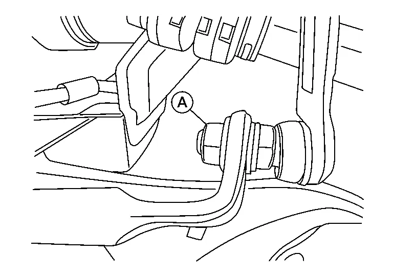
Remove bolt (A) and separate steering intermediate shaft (1) from steering gear (2).

CAUTION:
With steering linkage disconnected, spiral cable may snap by turning steering wheel beyond the limited number of turns. Secure steering wheel during removal of stabilizer.
Remove steering gear heat shield.
Remove steering gear bolts. Refer to Exploded View.
Position steering gear forward.
Remove stabilizer connecting rod upper nuts (A) from front coil spring and struts (LH/RH).

Remove stabilizer connecting rod lower nuts (A) from stabilizer, and remove stabilizer connecting rods (LH/RH).
Remove bolts ( ) from stabilizer clamps, and then remove stabilizer clamps and stabilizer bushings from front suspension member.

Remove stabilizer from (LH) side of Nissan Murano vehicle.
INSTALLATION
Installation is in reverse order of removal.
CAUTION:
-
With steering linkage disconnected, spiral cable may snap by turning steering wheel beyond the limited number of turns. Secure steering wheel during installation of stabilizer.
-
Do not reuse stabilizer connecting rod nuts.
 NOTE:
NOTE:
Align the slit on steering intermediate shaft with projection on steering gear. Connect surface (A) to surface (B).

CAUTION:
When connecting steering intermediate shaft (1) to steering gear (2), first finger-tighten joint retaining bolt (A) then tighten to specification. The joint retaining bolt is directional. Refer to Exploded View.
WARNING:
After torquing outer socket nut, be sure to install cotter pin through outer socket stud hole and bend cotter pin around outer socket stud.
-
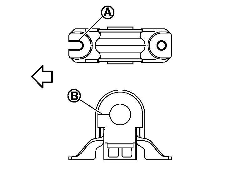
Install stabilizer clamp so that notch (A) is facing front of vehicle (
 ).
).
-
Install stabilizer bushing so that slit (B) is facing front of Nissan Murano vehicle (
). -
Check wheel alignment. Refer to Inspection.
-
Adjust neutral position of steering angle sensor. Refer to Description.
 Transverse Link
Exploded View
1.
Transverse link
2.
Front suspension member
Removal and Installation
REMOVALRemove steering knuckle with wheel hub and bearing...
 Steering Knuckle
Exploded View
1.
Cotter pin
2.
Nut retainer
3.
Disc brake rotor
4.
Wheel hub and bearing
5.
Wheel stud
6.
Splash guard
7.
Steering knuckle
Front
Removal and Installation
REMOVALRemove front wheel hub and bearing...
Other information:
Nissan Murano (Z52) 2015-2024 Service Manual: Rear Wheel Sensor
Exploded View RH Side 1. Rear wheel sensor A. Rear wheel sensor bracket B. Clip C. Harness connector D. Refer to Removal and Installation. Front LH Side 1. Rear wheel sensor A. Harness connector B. Clip C. Rear wheel sensor bracket D...
Nissan Murano (Z52) 2015-2024 Service Manual: P0443 Evap Canister Purge Volume Control Solenoid Valve
DTC Description DTC DETECTION LOGIC The canister purge flow is detected during the vehicle is stopped while the engine is running, even when EVAP canister purge volume control solenoid valve is completely closed. The canister purge flow is detected during the specified driving conditions, even when EVAP canister purge volume control solenoid valve is completely closed...
Categories
- Manuals Home
- Nissan Murano Owners Manual
- Nissan Murano Service Manual
- All-Wheel Drive (AWD) (if so equipped)
- Fuel recommendation
- System malfunction
- New on site
- Most important about car
Driver and passenger supplemental knee air bag

Driver’s side
The knee air bag is located in the knee bolster, on the driver’s and passenger’s side. All of the information, cautions and warnings in this manual apply and must be followed. The knee air bag is designed to inflate in higher severity frontal collisions, although it may inflate if the forces in another type of collision are similar to those of a higher severity frontal impact. It may not inflate in certain collisions.

Passenger’s side