Nissan Murano: Removal and Installation / Transmission Range Switch
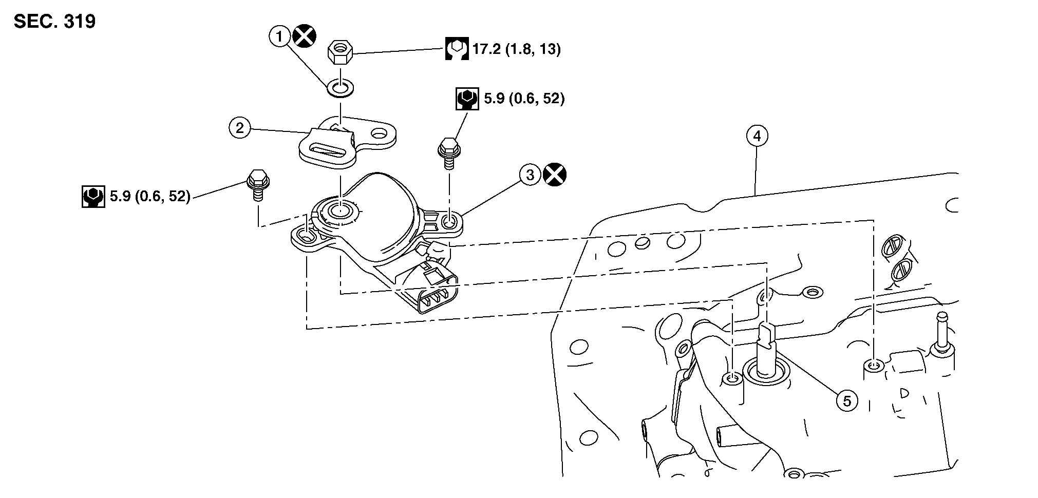
| 1. | Lock washer | 2. | Manual lever | 3. | Transmission range switch |
| 4. | CVT | 5. | Manual shaft |
REMOVAL
Remove air cleaner and air duct. Refer to Removal and Installation.
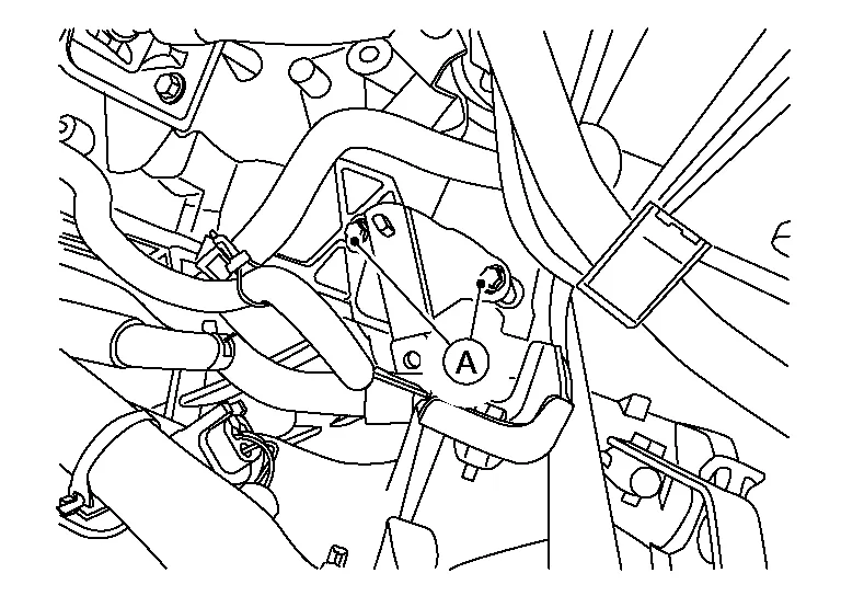
Remove control cable nut (A).
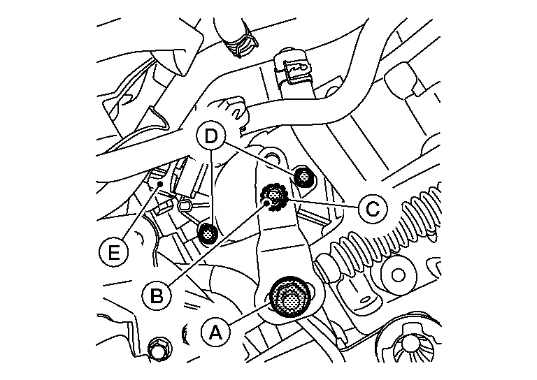
Remove manual lever nut (B) and lock washer (C) from the bracket and remove manual lever.
CAUTION:
Do not reuse lock washer.
Remove bolts (D) and disconnect harness connector (E).
Remove transmission range switch.
CAUTION:
Do not reuse transmission range switch.
INSTALLATION
Install new transmission range switch.
CAUTION:
Do not reuse transmission range switch.
 NOTE:
NOTE:
Ensure bolts are loose enough for the transmission range switch to pivot easily.
Install the manual lever.
NOTE:
Do not install the nut or the lock washer.
Use the manual lever to shift the CVT into Neutral (N).
Remove the manual lever.
Assemble Tool.
| Tool number | : — (J-52306) |
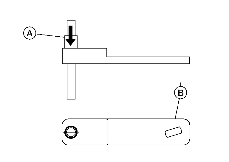
NOTE:
Ensure pin (A) is threaded into gauge (B) as shown.
Place Tool (A) onto the manual shaft (B) while inserting its pin in the hole of the transmission range switch.
| Tool number | : — (J-52306) |
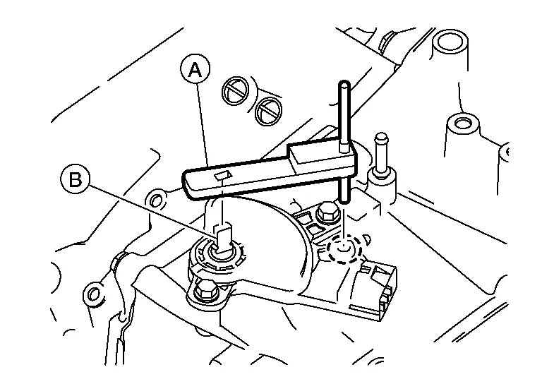
Tighten bolts (A) to specification and remove Tool. Refer to Exploded View.
| Tool number | : — (J-52306) |
Install the manual lever and lock washer and tighten nut to specification. Refer to Exploded View.
CAUTION:
Do not reuse lock washer.
Install remaining components in reverse order of removal.
INSPECTION AFTER INSTALLATION
NOTE:
-
Ensure shift selector cannot be shifted out of Park (P) without depressing the brake pedal.
-
Ensure shift selector can be shifted out of Park (P) with the brake pedal depressed.

 Cvt Shift Selector
Exploded View
1.
Shift selector handle
2.
Shift selector handle clip
3.
Control cable
4
Shift selector assembly
5.
Shift selector handle cover
Removal and Installation
REMOVALApply the parking brake...
Other information:
Nissan Murano (Z52) 2015-2024 Service Manual: Front Lower Link
Exploded View 1. Rear shock absorber 2. Rear suspension member 3. Front lower link 4. Rear suspension link protector 5. Rear knuckle Pawl Front Removal and Installation REMOVALRemove the front under cover...
Nissan Murano (Z52) 2015-2024 Service Manual: Front Axle :: Precaution. Precautions
Precaution for Supplemental Restraint System (SRS) "AIR BAG" and "SEAT BELT PRE-TENSIONER" The Supplemental Restraint System such as “AIR BAG” and “SEAT BELT PRE-TENSIONER”, used along with a front seat belt, helps to reduce the risk or severity of injury to the driver and front passenger for certain types of collisions...
Categories
- Manuals Home
- Nissan Murano Owners Manual
- Nissan Murano Service Manual
- Fuel recommendation
- Warning lights
- Passenger compartment
- New on site
- Most important about car
Unfastening the seat belts. Checking seat belt operation
Unfastening the seat belts

To unfasten the seat belt, press the button
on the buckle  . The seat belt
automatically
retracts.
. The seat belt
automatically
retracts.