
Nissan Murano: Rear Suspension :: Removal and Installation / Front Lower Link

| 1. | Rear shock absorber | 2. | Rear suspension member | 3. | Front lower link |
| 4. | Rear suspension link protector | 5. | Rear knuckle |  |
Pawl |
 |
Front |
REMOVAL
Remove the front under cover. Refer to Removal and Installation.
Support the front of vehicle with a suitable jack.
WARNING:
Place a suitable jack under the center of the front suspension member.
CAUTION:
Do not damage the front suspension member with the suitable jack.
Remove the rear wheel and tire using power tool. Refer to Removal and Installation.
Support the rear lower link with a suitable jack.
WARNING:
Place a suitable jack under the outer end of the rear lower link.
CAUTION:
Do not damage the rear lower link with the suitable jack.
Support the rear knuckle with a suitable jack.
WARNING:
Place a suitable jack under the center of the rear knuckle.
CAUTION:
Do not damage the rear knuckle with the suitable jack.
Put alignment marks on the adjusting bolt and on the rear suspension member.

CAUTION:
Use paint or an equivalent for alignment marks. Do not scratch the surface.
Remove the lower shock absorber bolt using power tool. Refer to Exploded View.
Support the rear lower link with a suitable jack.
WARNING:
Place a suitable jack under the outer end of the rear lower link.
CAUTION:
Do not damage the rear lower link with the suitable jack.
Remove the rear lower link nut and bolt from the rear knuckle using power tool. Refer to Exploded View.
Slowly lower the suitable jack supporting the rear lower link. Remove the upper seat, the coil spring, and the lower rubber seat from the rear lower link. Refer to Exploded View.
Remove the coil spring. Refer to Exploded View.
Remove the front lower link nut and bolt from the rear suspension member using power tool.
Remove the front lower link nut and bolt from the rear knuckle using power tool.
Remove the rear suspension link protector by pulling forward and releasing pawls.
Remove the front lower link.
INSTALLATION
Installation is in the reverse order of removal.
CAUTION:
Do not reuse the front lower link nuts.
-
Perform the final tightening of the parts under unladen conditions with the tires on level ground.
-
Check the wheel alignment. Refer to Inspection.
-
Adjust the neutral position of the steering angle sensor. Refer to Description.
 Radius Rod
Exploded View
1.
Rear suspension member
2.
Radius rod
3.
Rear knuckle
Front
Removal and Installation
REMOVALRemove the rear wheel and tire using power tool...
 Rear Stabilizer
Exploded View
1.
Rear suspension arm
2.
Stabilizer connecting rod
3.
Stabilizer
4.
Stabilizer bushing
5.
Stabilizer clamp
Front
Removal and Installation
REMOVALRemove the rear under covers (LH/RH)...
Other information:
Nissan Murano (Z52) 2015-2024 Service Manual: Input Speed Sensor
Exploded View 1. Input speed sensor 2. O-ring 3. Transaxle assembly : Apply CVT fluid Removal and Installation REMOVALRemove the battery tray. Refer to Removal and Installation. Remove the starter motor. Refer to Removal and Installation...
Nissan Murano (Z52) 2015-2024 Owners Manual: Turning the Traffic Sign Recognition (TSR) system on and off
Perform the following steps to enable or disable the TSR system. Press the button until “Settings” displays in the vehicle information display and then press the OK button. Use the button to select “Driver Assistance.” Then press the OK button...
Categories
- Manuals Home
- Nissan Murano Owners Manual
- Nissan Murano Service Manual
- Shift lock release
- Intelligent Forward Collision Warning (I-FCW)
- How to enable/disable the LDW system
- New on site
- Most important about car
Vehicle security system
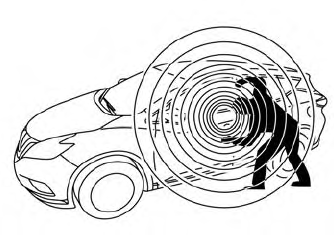
Your vehicle has two types of security systems:
Vehicle security system NISSAN Vehicle Immobilizer SystemThe vehicle security system provides visual and audible alarm signals if someone opens the doors, liftgate or the hood when the system is armed. It is not, however, a motion detection type system that activates when a vehicle is moved or when a vibration occurs.
