
Nissan Murano: Meters and gauges / Tachometer
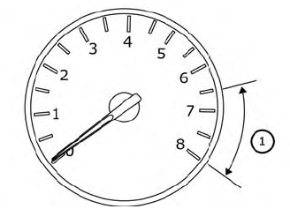
The tachometer indicates engine speed in
revolutions per minute (rpm). Do not rev
engine into the red zone  .
.
CAUTION
When engine speed approaches the red zone, reduce engine speed. Operating the engine in the red zone may cause serious engine damage.
 Speedometer and odometer
This vehicle is equipped with a speedometer
and odometer. The speedometer is
located on the right side of the meter cluster.
The odometer is located within the vehicle
information display...
 Engine coolant temperature gauge
The gauge indicates the engine coolant
temperature.The engine coolant temperature
is within the normal range when
the gauge needle points within the zone
shown in the illustration...
Other information:
Nissan Murano (Z52) 2015-2024 Service Manual: Ascd Indicator
Component Function Check CHECK ASCD INDICATOR FUNCTION Check ASCD indicator under the following conditions. ASCD INDICATOR CONDITION SPECIFICATION CRUISE Ignition switch: ON MAIN switch: Pressed at the 1st time → at the 2nd time ON → OFF Is the inspection result normal? YES>> INSPECTION END NO>> Proceed to Diagnosis Procedure...
Nissan Murano (Z52) 2015-2024 Service Manual: Parking Brake Release Warning Chime
Parking Brake Release Warning Chime SYSTEM DIAGRAMWARNING OPERATION CONDITIONSIf all of the following conditions are fulfilled: Operation conditions Ignition switch ON Parking brake During the operation (parking brake switch ON). Nissan Murano Vehicle speed Approximately 4...
Categories
- Manuals Home
- Nissan Murano Owners Manual
- Nissan Murano Service Manual
- Power Steering Fluid (PSF)
- Vehicle Dynamic Control (VDC) OFF switch
- How to enable/disable the LDW system
- New on site
- Most important about car

Copyright © 2026 www.nimurano.com