Nissan Murano: System / Parking Brake Release Warning Chime
Nissan Murano (Z52) 2015-2024 Service Manual / Driver Information & Multimedia / Warning Chime System :: System Description / System / Parking Brake Release Warning Chime
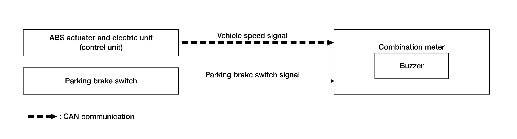
SYSTEM DIAGRAM
WARNING OPERATION CONDITIONS
If all of the following conditions are fulfilled:
| Operation conditions | |
|---|---|
| Ignition switch | ON |
| Parking brake | During the operation (parking brake switch ON). |
| Nissan Murano Vehicle speed | Approximately 4.3 MPH (7 km/h) or more. |
WARNING CANCEL CONDITIONS
Warning is canceled if any of the following conditions are fulfilled:
| Operation conditions | |
|---|---|
| Ignition switch | OFF |
| Parking brake | Release condition (parking brake switch OFF). |
| Nissan Murano Vehicle speed | Approximately 1.9 MPH (3 km/h) or less. |
SIGNAL PATH
Combination meter sounds integrated buzzer when it judges that parking brake release warning chime is necessary from signals below.
| Signal name | Signal source |
|---|---|
| Ignition switch signal | — |
| Parking brake switch signal | Parking brake switch  Combination meter Combination meter |
| Nissan Murano Vehicle speed signal | ABS actuator and electric unit (control unit)  Combination meter Combination meter |
 Light Reminder Warning
Light Reminder Warning
SYSTEM DIAGRAMWARNING CHIME OPERATION CONDITIONSIf all of the following conditions are fulfilled: Operation conditions
Ignition switch
OFF
Combination switch (Lighting switch)
1st or 2nd position
Driver side door
Open [front door switch LH ON]
WARNING CHIME CANCEL CONDITIONSWarning is canceled if any of the following conditions are fulfilled: Operation conditions
Ignition switch
ON
Combination switch (Lighting switch)
OFF or AUTO position
Driver side door
Close [front door switch LH OFF]
SIGNAL PATH
BCM requires warning chime output to combination meter when it judges light reminder warning chime is necessary from signals below...
 Seat Belt Warning
Seat Belt Warning Chime
SYSTEM DIAGRAMWARNING OPERATION CONDITIONSFront Seat BeltsIf all of the following conditions are fulfilled: Operation conditions
Ignition switch
ON
Nissan Murano Vehicle speed
Approximately 9...
Other information:
Nissan Murano (Z52) 2015-2024 Service Manual: Wheel and Tire
Exploded View 1. Wheel and tire 2. Wheel nut Removal and Installation REMOVALRemove wheel nuts using power tool. Remove wheel and tire.INSTALLATIONInstallation is in reverse order of removal.CAUTION: When installing wheel nuts, tighten them diagonally by dividing the work two or three times in order to prevent wheels from developing any distortion...
Nissan Murano (Z52) 2015-2024 Service Manual: Steering Control System :: Precaution. Precautions
Precaution for Supplemental Restraint System (SRS) "AIR BAG" and "SEAT BELT PRE-TENSIONER" The Supplemental Restraint System such as “AIR BAG” and “SEAT BELT PRE-TENSIONER”, used along with a front seat belt, helps to reduce the risk or severity of injury to the driver and front passenger for certain types of collisions...
Categories
- Manuals Home
- Nissan Murano Owners Manual
- Nissan Murano Service Manual
- High Beam Assist (if so equipped)
- Jacking up vehicle and removing the damaged tire
- Rear bench seat adjustment
- New on site
- Most important about car
Fuel gauge

The gauge indicates the approximate fuel level in the tank.
The gauge may move slightly during braking, turning, acceleration, or going up or down hills.
The gauge needle returns to 0 (Empty) after the ignition switch is placed in the OFF position.
Copyright © 2026 www.nimurano.com