Nissan Murano: System Description / System
SYSTEM DIAGRAM
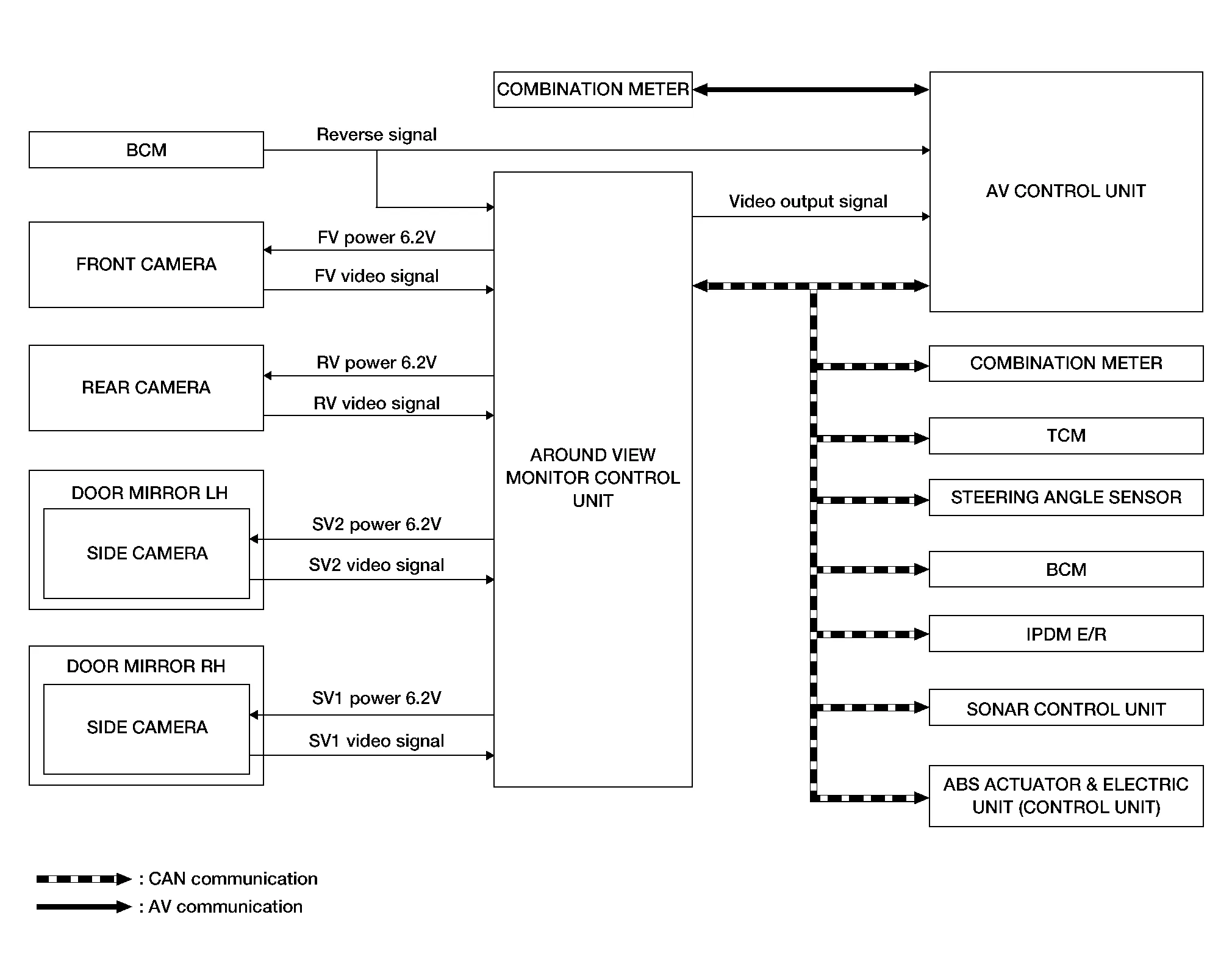
Around View Monitor Control Unit Input Signal (CAN Communication)
| Transmit unit | Signal name |
|---|---|
| ABS actuator and electrical unit (Control unit) | Wheel speed signal |
| AV control unit | Camera switch signal |
| BCM | Door switches state signal |
| Combination meter |
|
| IPDM E/R | Battery voltage signal |
| Sonar control unit | Sonar detection display request signal |
| Steering angle sensor | Steering angle signal |
| TCM | Transmission range indication signal |
DESCRIPTION
-
This system is equipped with wide-angle cameras on the front, rear and right and left door mirrors.
-
Images from front view, rear view, front-side view (RH side), and birds-eye view are displayed to monitor the Nissan Murano vehicle surroundings.
-
Around view monitor control unit expands the image received from each camera to create each view.
-
The sonar indicator is displayed on display (superimposed on the camera image) in combination with the camera assistance sonar system to warn of the approach of an obstacle.
-
Camera image is displayed on the display when an obstacle is detected by sonar system.
-
In front view and rear view, the Nissan Murano vehicle width, distance lines and predictive course lines are displayed.
-
In front-side view, the Nissan Murano vehicle distance guiding line and vehicle width guiding line are displayed.
-
Birds-eye view converts the images from the cameras into an overhead view and displays the status of the Nissan Murano vehicle on the display control unit. The vehicle icon that is displayed in the birds-eye view is depicted by the around view monitor control unit.
-
Moving Object Detection (MOD) is adopted and detects moving objects according to camera image and notifies the detection result to the driver.
INTELLIGENT AROUND VIEW MONITOR DISPLAY
The Intelligent around view monitor combines and displays travel direction view (front or rear), front-side view and birds-eye view.
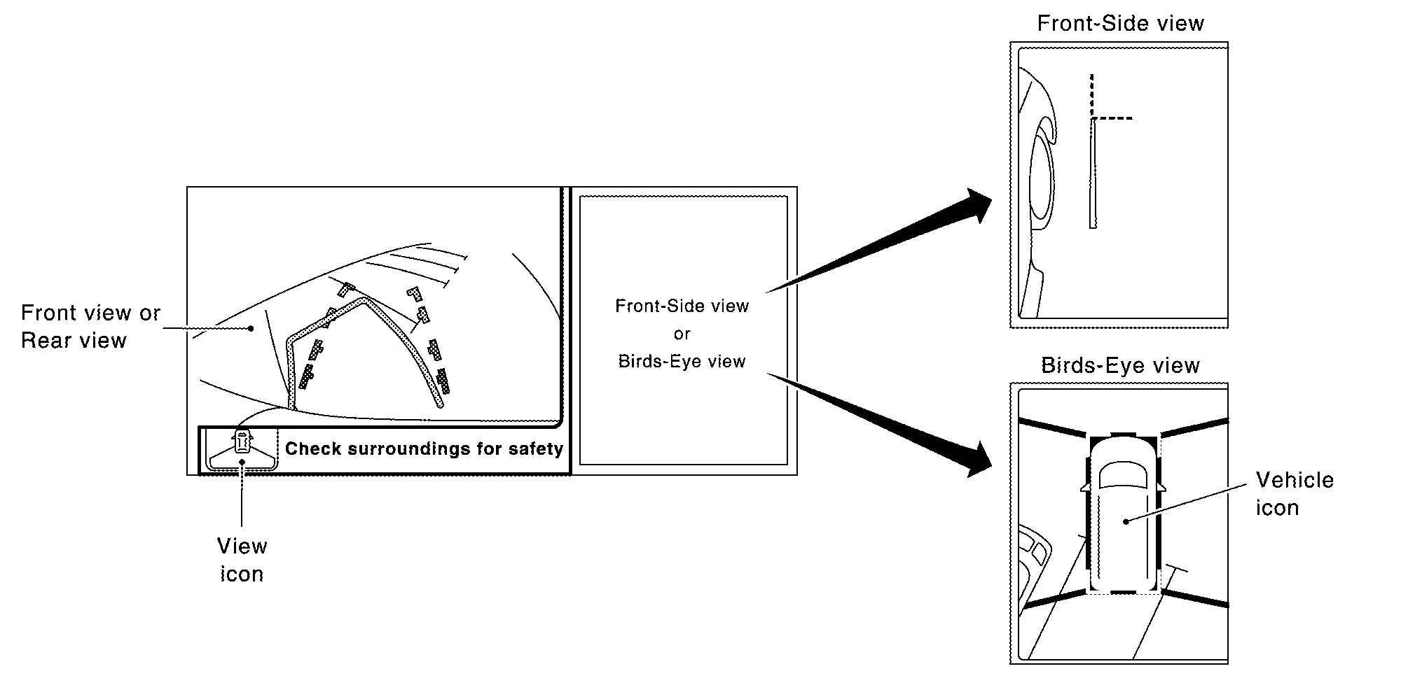
OPERATION DESCRIPTION
-
The Intelligent around view monitor operates by pressing the CAMERA switch on the AV control unit or by shifting to the R (reverse) position.
-
When the shift lever is in any position other than R (reverse) and the CAMERA switch is pressed, the screen displays front travel direction view and birds-eye view. Pressing the CAMERA switch again changes birds-eye view to front-side view
-
When the shift lever is placed in R (reverse), the screen displays rear travel direction view and birds-eye view. Pressing the CAMERA switch changes birds-eye view to front-side view
-
In birds-eye view, the blind spot area is displayed in black to show the border of the camera images. In addition, red fixed lines are displayed in the 4 corners of the Nissan Murano vehicle icon. After pressing the CAMERA switch for the first time or placing the shift lever switch in R (reverse) for the first time, the blind spot area is highlighted in yellow for 3 seconds and the red fixed lines blink five times.
-
With the shift lever in any position other than R (reverse), the Intelligent around view monitor screen display is cancelled 3 minutes after pressing the CAMERA switch. The screen returns to the AV control unit display.
-
With the shift lever in R (reverse) position, the Intelligent around view monitor screen display remains on constantly. To return to the AV control unit display, place the shift lever in any position other than R (reverse).
-
If camera image calibration is incomplete, the applicable camera position is indicated as an error on the birds-eye view display.
 NOTE:
NOTE:
Calibration is necessary when replacing each camera or when replacing around view monitor control unit.
Intelligent around view monitor screen transition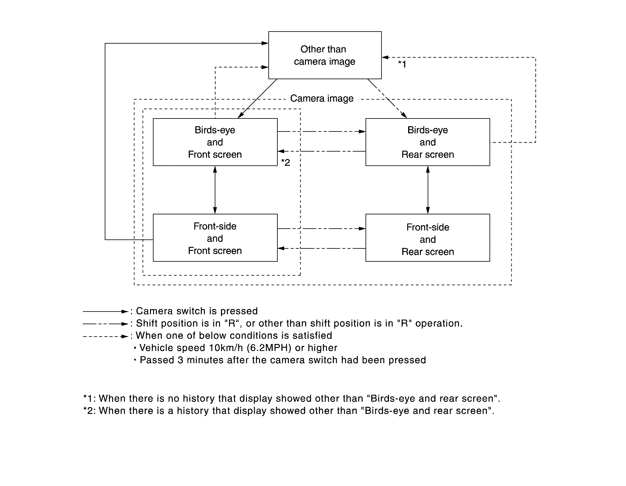
Front View
-
The front view image improves the visibility of obstacles in front of the vehicle and assists driving by displaying images from birds-eye view and front-side view.
-
The front view image displays the Nissan Murano vehicle width guiding line and vehicle distance guiding line, in addition to the predictive course line according to the steering angle.
-
If the steering angle is within approximately 90 degrees, the predictive course lines on the left/right side are displayed. If the steering angle exceeds approximately 90 degrees, only the predictive course line on the outside is displayed (opposite side of steering direction).
-
The around view monitor control unit receives the steering angle signal from steering angle sensor via CAN communication, and controls the direction and distance of the predictive course line.
-
ON/OFF setting of predictive course line can be performed using CONSULT.
Front view guiding lines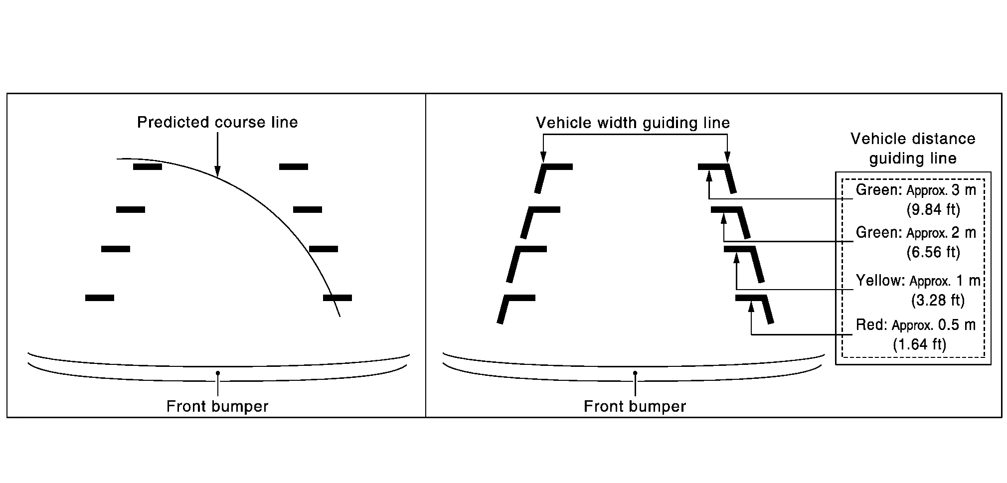
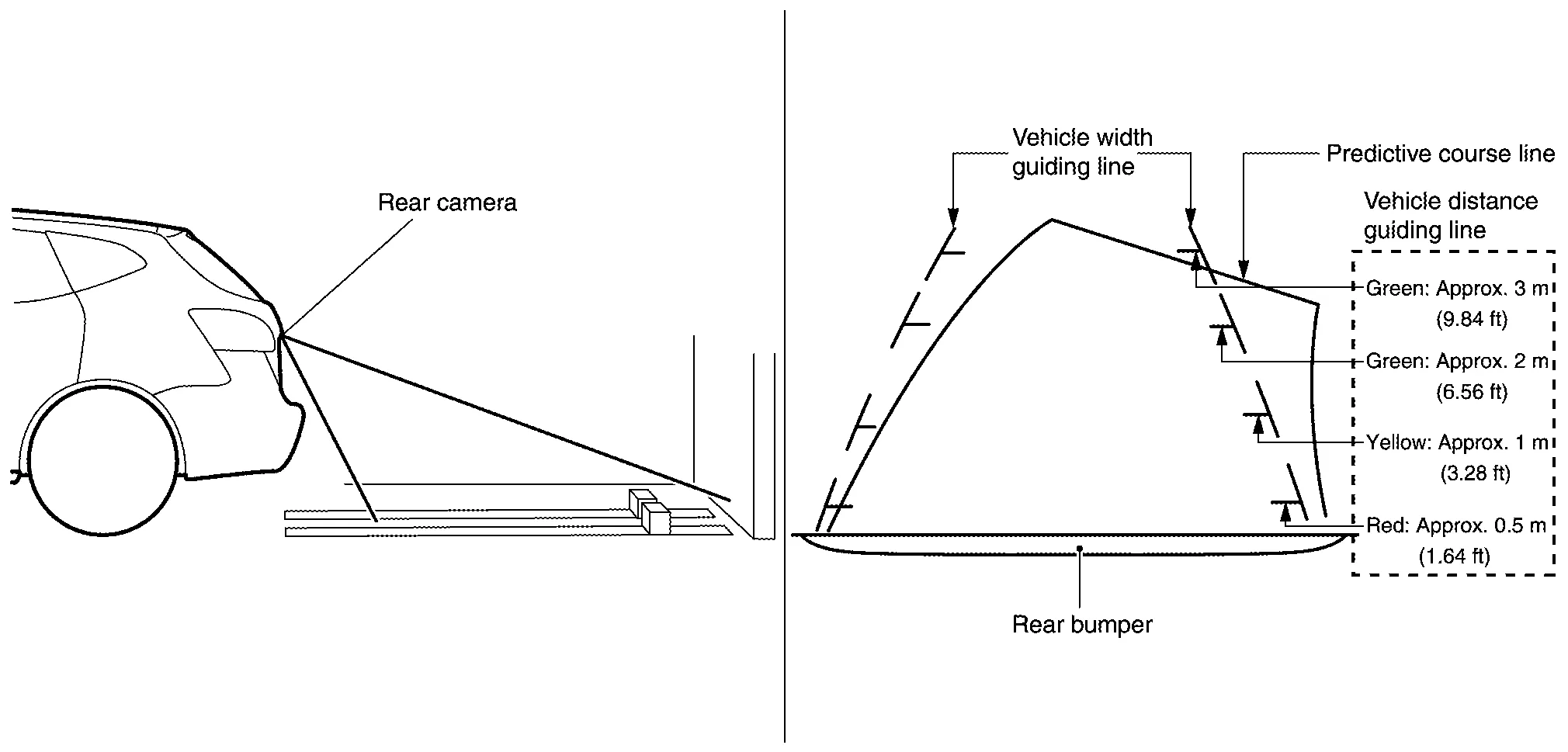
Rear View
-
The rear view image improves the visibility of obstacles in the rear of the vehicle and assists backing and parking by displaying images from birds-eye view and rear view.
-
The rear view image displays the Nissan Murano vehicle width guiding line and vehicle distance guiding line, in addition to the predictive course line according to the steering angle.
NOTE:
The predictive course line is not displayed at the steering neutral position.
-
The around view monitor control unit receives the steering angle signal from steering angle sensor via CAN communication, and controls the direction and distance of the predictive course line.
-
ON/OFF setting of predictive course line can be performed using CONSULT.
Rear view guiding lines
Front-side View
-
The front-side view image improves the visibility of obstacles in the front RH side of the Nissan Murano vehicle and assists backing and parking.
-
The front-side view image displays the vehicle distance guiding line and Nissan Murano vehicle width guiding line.
Front-side view area and guiding line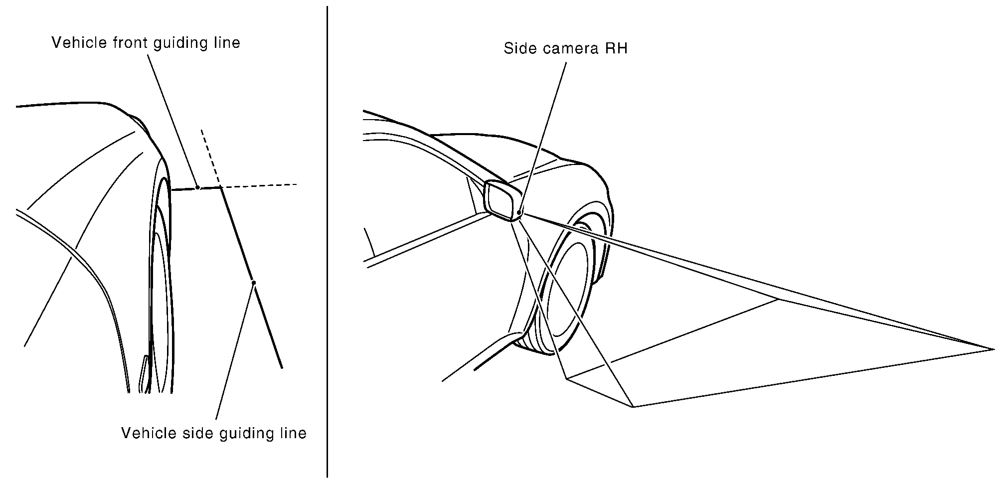
Birds-eye View
Birds-Eye View
-
The birds-eye view image improves the visibility of obstacles all around the vehicle and assists backing and parking.
-
The images from the four cameras are converted into an overhead view, and the surroundings of the Nissan Murano vehicle are displayed.
-
The blind spot area is displayed on the image to specify the boundary of the four cameras.
Birds-Eye view display image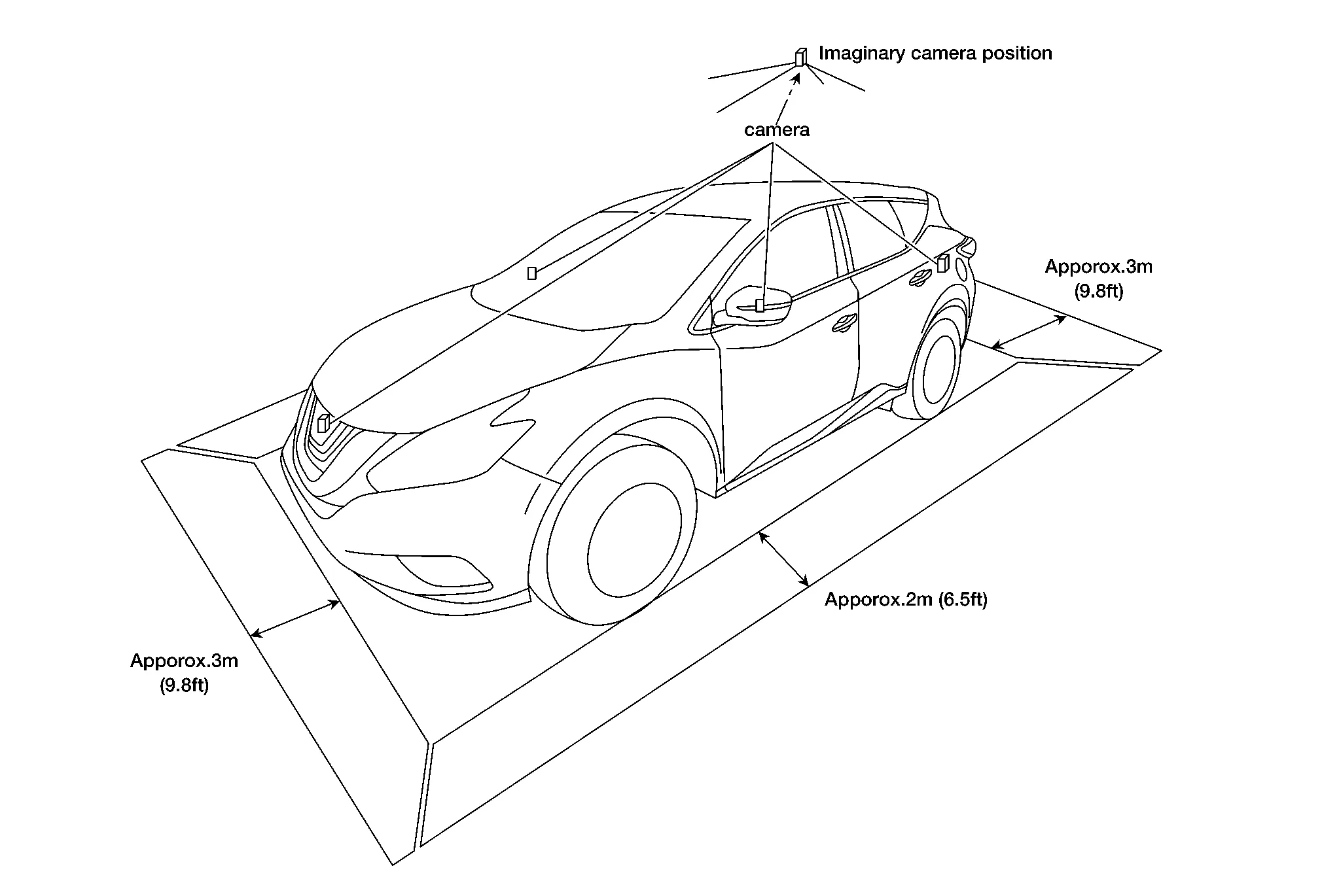
Birds-Eye view display area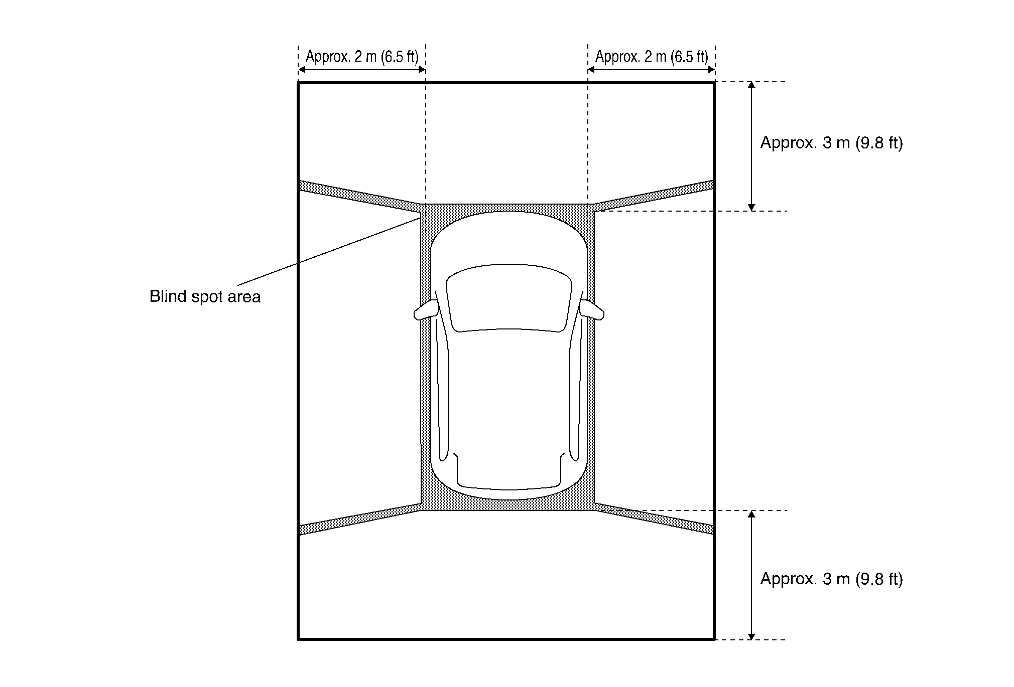
Moving Object Detection (MOD)
-
Moving Object Detection (MOD) is a function that notifies the driver of the presence of moving objects in the area around the Nissan Murano vehicle. MOD detects moving objects from camera image, illuminates frame of view in yellow whenever “MOD” icon is displayed in blue.
-
Around view monitor control unit superimposes yellow frame line on camera image signal and outputs it to AV control unit display when moving objects are detected.
-
Around view monitor control unit detects moving objects from camera image according to an image recognition method called optical flow.
-
MOD does not detect a background as a moving object when the Nissan Murano vehicle moves (when whole screen moves) but detects a moving object when an actual moving object is displayed on screen.
-
Color of “MOD” icon indicates whether or not MOD is operative. “MOD” icon is displayed as shown in the following table. when MOD is operative, “MOD” icon is displayed in blue. when MOD is not operative, “MOD” icon is displayed in gray.
View Shift position P, N or D position R position “MOD” icon display Birds-Eye view and rear view Birds-Eye view — Gray Rear view Blue Birds-Eye view and front view Birds-Eye view Blue — Front view Gray Side view and rear view Side view — × Rear view Blue Side view and front view Side view × — Front view Blue ×: Icon is not displayed.
—: View is not displayed in each shift position (D position and R position).
-
MOD illuminates frame of view in yellow when any of the conditions in the following table are satisfied:
Operation Condition View where MOD is operative Shift position Nissan Murano Vehicle speed P or N position 0 km/h Birds-Eye view D position 0 km/h (0 MPH) or more - less than 8 km/h (5 MPH) Front view R position 0 km/h (0 MPH) or more - less than 8 km/h (5 MPH) Rear view -
MOD does not operate or stops operation when any of the conditions in the following table are satisfied:
Operation stop condition Note Door open -
MOD does not stop operation for front view.
-
Operation stops for rear view while back door is open.
-
Operation stops for Bird’s-Eye view when any door is open.
-
CAMERA IMAGE OPERATION PRINCIPLE
-
If the information written to around view monitor control unit and the information from the camera do not match, the applicable camera position is indicated as an error on the Birds-Eye view display. (Calibration operation is necessary when replacing each camera or when replacing around view monitor control unit.)
-
Around view monitor control unit receives the camera switch signal from multifunction switch via CAN communication by pressing the “CAMERA” button.
-
Around view monitor control unit that receives the camera button signal supplies the power to each camera and inputs the camera image from each camera.
-
When the shift lever switch is in the reverse position, around view monitor control unit receives the reverse signal, supplies the power to each camera, and inputs the camera image from each camera.
-
Around view monitor control unit that receives the camera image signal from each camera cuts out the required screen for each view, superimposes the camera image, Nissan Murano vehicle icon, guiding lines, sonar indicator and “MOD” icon and outputs them to the display control unit.
 Component Parts. Intelligent Around View Monitor with Navigation System
Component Parts Location
No. Component Function
1.
Rear camera
Refer to Rear Camera.
2.
Door mirror RH (side camera)
Refer to Side Cameras...
 Diagnosis System (around View Monitor Control Unit)
CONSULT Function
CONSULT FUNCTIONSCONSULT performs the following functions via communication with the around view monitor control unit. Direct Diagnostic Mode Description
ECU Identification
The around view monitor control unit part number is displayed...
Other information:
Nissan Murano (Z52) 2015-2024 Service Manual: Ecm, Ipdm E/r, Bcm
L..
Nissan Murano (Z52) 2015-2024 Owners Manual: High Beam Assist (if so equipped)
The High Beam Assist system will operate when the vehicle is driven at speeds of approximately 25mph(40 km/h) and above. If an oncoming vehicle or leading vehicle appears in front of your vehicle when the headlight high beam is on, the headlight will be switched to the low beamautomatically...
Categories
- Manuals Home
- Nissan Murano Owners Manual
- Nissan Murano Service Manual
- Tire rotation
- How to enable/disable the LDW system
- Warning lights
- New on site
- Most important about car
Autolight system
The autolight system allows the headlights to turn on and off automatically. The autolight system can:
Turn on the headlights, front parking, tail, license plate and instrument panel lights automatically when it is dark. Turn off all the lights (except daylight running lights) when it is light. Keep all the lights on for a period of time after you place the ignition switch in the OFF position and all doors are closed.