Nissan Murano: System Description / Component Parts. Intelligent Around View Monitor with Navigation System

| No. | Component | Function |
|---|---|---|
| 1. | Rear camera | Refer to Rear Camera. |
| 2. | Door mirror RH (side camera) | Refer to Side Cameras. |
| 3. | ABS actuator and electric unit (Control unit) |
Provides around view monitor control unit with wheel speed signal via CAN communication. Refer to Component Parts Location for detailed component location. |
| 4. | Front camera | Refer to Front Camera. |
| 5. | TCM (Transmission Control Module) |
Provides around view monitor control unit with transmission range indication signal via CAN communication. Refer to Component Parts Location for detailed component location. |
| 6. | IPDM E/R (Intelligent Power Distribution Module Engine Room) |
Provides around view monitor control unit with battery voltage signal via CAN communication. Refer to Component Parts Location for detailed component location. |
| 7. | Door mirror LH (side camera) | Refer to Side Cameras. |
| 8. | Sonar control unit | Refer to Sonar Control Unit. |
| 9. | AV control unit | Refer to AV Control Unit. |
| 10. | BCM (Body Control Module) | Refer to BCM. |
| 11. | Combination meter | Refer to Combination Meter. |
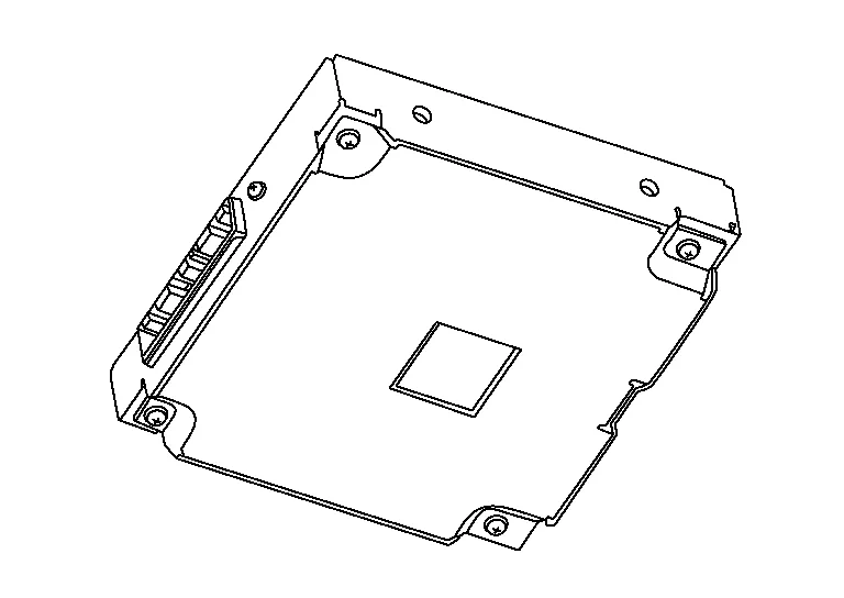
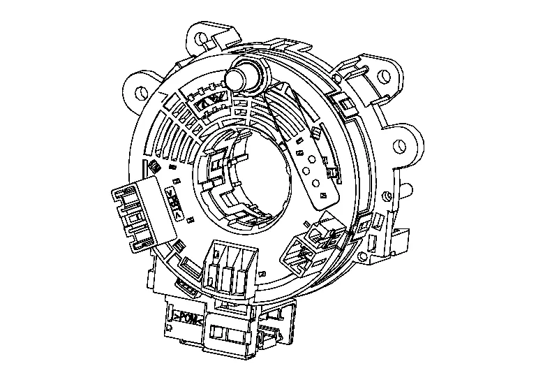
| 12. | Steering angle sensor | Refer to Steering Angle Sensor. |
| 13. | Around View® Monitor control unit | Refer to Around View Monitor Control Unit. |
-
A 8-inch color display with multi-touch control, an AM/FM HD electronic tuner radio with RDS, CD drive, audio amplifier and camera controller are integrated into the AV control unit.

-
The 8-inch color display is a high resolution monitor that includes touch panel functions.
-
The around view monitor control unit is installed behind the front auxiliary input jacks.
-
Nissan Murano Vehicle width guide lines, predicted course line, vehicle front guiding line and vehicle side line, and vehicle icon are displayed and combined with camera images.
-
The rear camera is installed next to the license plate lamp.

-
Power is supplied from the around view monitor control unit.
-
The side cameras are installed in the door mirrors.

-
Power is supplied from the around view monitor control unit.
-
The front camera is installed in the front grille.

-
Power is supplied from the around view monitor control unit.
The combination meter displays the sonar indicator.

BCM sends the reverse signal to the around view monitor control unit and AV control unit.

-
Steering sensor is installed to the spiral cable.
-
Steering angle sends the steering signal necessary for predictive course line via CAN communication.

 System
System Description
SYSTEM DIAGRAMAround View Monitor Control Unit Input Signal (CAN Communication)Transmit unitSignal name
ABS actuator and electrical unit (Control unit)
Wheel speed signal
AV control unit
Camera switch signal
BCM
Door switches state signal
Combination meter
Setting change request signal
Hand brake switch signal
IPDM E/R
Battery voltage signal
Sonar control unit
Sonar detection display request signal
Steering angle sensor
Steering angle signal
TCM
Transmission range indication signal
DESCRIPTION
This system is equipped with wide-angle cameras on the front, rear and right and left door mirrors...
Other information:
Nissan Murano (Z52) 2015-2024 Service Manual: Removal and Installation. 3ch Can Gateway
Removal and Installation CAUTION: Before replacing 3CH CAN gateway, perform “Before Replace ECU” of “Read / Write Configuration” to save or print current Nissan Murano vehicle specification. Refer to Description. REMOVALRemove the glove box assembly and housing...
Nissan Murano (Z52) 2015-2024 Service Manual: Luggage Side Lower Finisher
Removal and Installation REMOVALRemove back door kicking plate. Refer to Removal and Installation. Remove rear kicking plate. Refer to Removal and Installation - Rear Kicking Plate. Remove luggage side upper finisher. Refer to Removal and Installation...
Categories
- Manuals Home
- Nissan Murano Owners Manual
- Nissan Murano Service Manual
- Jacking up vehicle and removing the damaged tire
- Fuel recommendation
- High Beam Assist (if so equipped)
- New on site
- Most important about car