Nissan Murano: Instrument Panel :: Removal and Installation / Steering Member Assembly
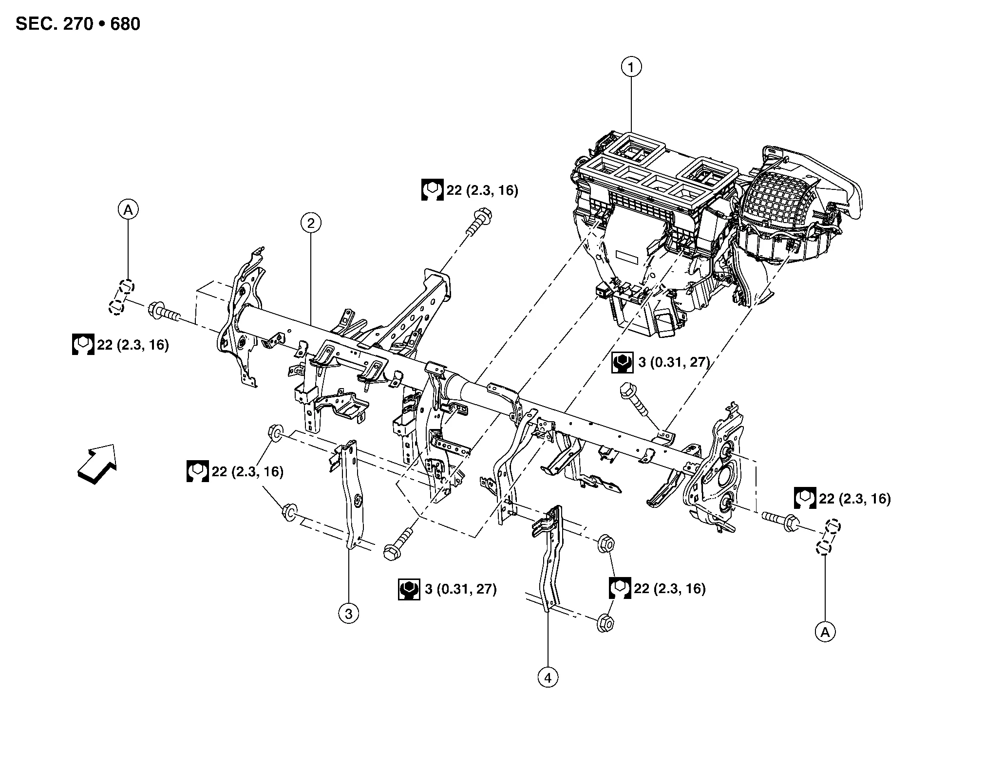
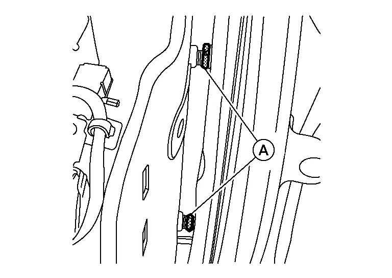
| 1. | Heating and cooling unit assembly | 2. | Steering member | 3. | Steering member brace (LH) |
| 4. | Steering member brace (RH) | A. | Steering member caps |  |
Pawl |
| Front |
REMOVAL
Remove front wiper drive assembly. Refer to Removal and Installation.
Remove steering member bolt in engine room. Refer to Exploded View.
Remove the instrument panel. Refer to Removal and Installation.
Remove the center console. Refer to Removal and Installation.
Remove the TCU mounting screws.
Disconnect the harness connector, and then remove the TCU.
Remove center floor duct clip and place center floor duct aside. Refer to Exploded View.
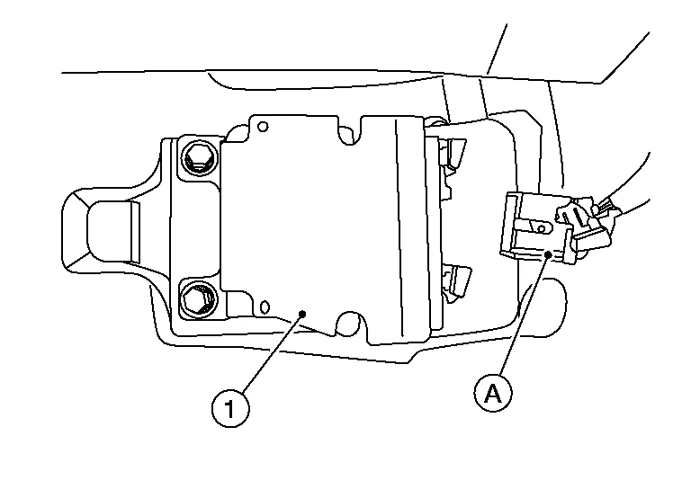
Disconnect harness connector (A) from the air bag diagnosis sensor unit (1).
Feed steering member harness through center console bracket.
Disconnect harness connector from the shift selector assembly and release harness retainers.
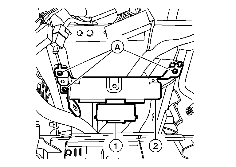
Remove screws (A) and the ADAS control unit (1) and the around view monitor control unit (2) as an assembly.
Remove the left knee air bag module. Refer to Removal and Installation.
Remove right knee air bag module. Refer to Removal and Installation.
Remove screws (A) from fuse box (1).
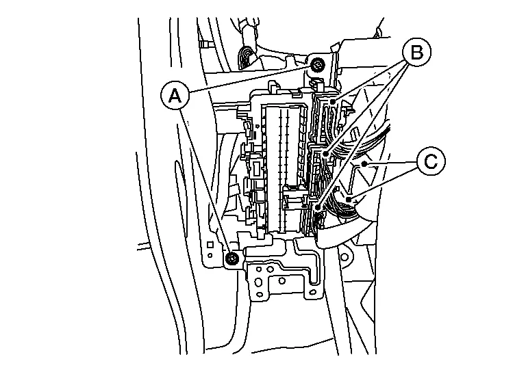
Disconnect front harness connectors (B) and front relays (C).
Disconnect main harness connectors from junction box (LH/RH). Refer to Harness Connector (lever locking type).
Disconnect the front door harness connector (LH/RH).
Remove the nut and bolt and separate the steering intermediate shaft from the steering column. Refer to Exploded View.
Remove nuts from steering member braces and remove steering member braces. Refer to Exploded View.
Disconnect all necessary harness connectors and release harness retainers.
Remove heating and cooling unit assembly bolts. Refer to Exploded View.
Remove steering member caps. Refer to Exploded View.
Remove steering member bolts. Refer to Exploded View.
Using a suitable tool, adjust spacers (A) and remove the steering member from Nissan Murano vehicle.
CAUTION:
Two people are required for removal to prevent damage to steering member.
INSTALLATION
Installation is in the reverse order of removal.
 NOTE:
NOTE:
If replacing steering member, transfer all of the necessary parts to the new steering member.

 Steering Column Covers
Removal and Installation
REMOVALRemove steering column cover screws (A).
NOTE:
Rotate steering wheel to access steering column cover screws.
Release steering column upper cover pawls using a suitable tool and remove...
Other information:
Nissan Murano (Z52) 2015-2024 Service Manual: Additional Service When Replacing Transaxle Assembly
Description Perform the following work after the transaxle assembly is replaced. For work procedure, refer to Work Procedure.NOTE: The CD provided with the new transaxle assembly contains important calibration data that must be installed with CONSULT after installation of the new transaxle assembly...
Nissan Murano (Z52) 2015-2024 Service Manual: B Terminal Circuit
Diagnosis Procedure CAUTION: Perform diagnosis under the condition that the engine cannot start by the following procedure: Remove fuel pump fuse. Crank or start the engine (where possible) until the fuel pressure is depleted. CHECK TERMINAL B POWER SUPPLY VOLTAGE Ignition switch OFF...
Categories
- Manuals Home
- Nissan Murano Owners Manual
- Nissan Murano Service Manual
- Turning the AEB system on/off
- Passenger compartment
- Jacking up vehicle and removing the damaged tire
- New on site
- Most important about car
LATCH (Lower Anchors and Tethers for CHildren) system

LATCH system lower anchor locations - bench seat
Your vehicle is equipped with special anchor points that are used with LATCH system compatible child restraints. This system may also be referred to as the ISOFIX or ISOFIX compatible system. With this system, you do not have to use a vehicle seat belt to secure the child restraint unless the combined weight of the child and child restraint exceeds 65 lbs. (29.5 kg). If the combined weight of the child and child restraint is greater than 65 lbs. (29.5 kg), use the vehicle’s seat belt (not the lower anchors) to install the child restraint. Be sure to follow the child restraint manufacturer’s instructions for installation.