Nissan Murano: Engine Mechanical :: Removal and Installation / Rear Timing Chain Case

| 1. | O-ring | 2. | Blind plug (if equipped) | 3. | Rear timing chain case |
| 4. | Cylinder block | 5. | O-ring | 6. | O-ring |
| A. | Refer to Removal and Installation. | Engine front |
CAUTION:
-
After removing timing chain, do not turn the crankshaft and camshaft separately, or the valves will strike the pistons.
-
Before removing the upper oil pan, remove the crankshaft position sensor (POS).
-
Be careful not to damage sensor edges.
REMOVAL
Remove the engine assembly. Refer to Removal and Installation (FWD) or Removal and Installation (AWD).
Remove upper oil pan. Refer to Removal and Installation (Upper Oil Pan).
Remove the front timing chain case. Refer to Removal and Installation.
Remove the timing chains (primary) and (secondary). Refer to Removal and Installation.
Remove the rear timing chain case.
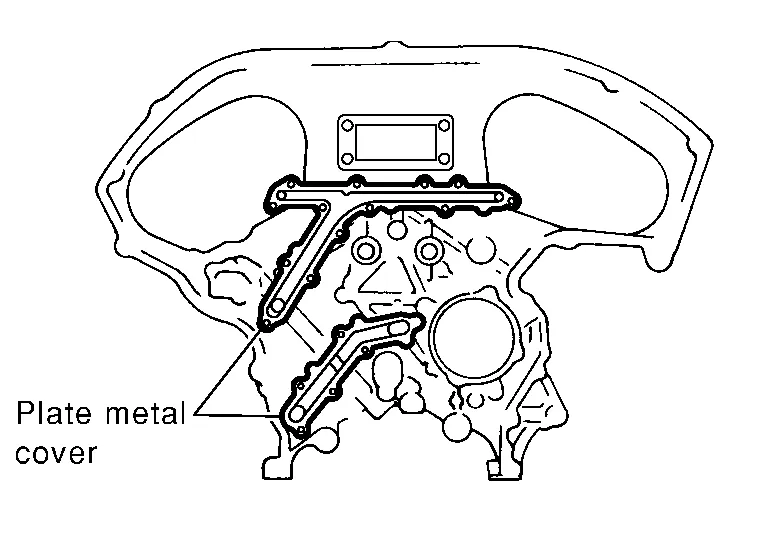
CAUTION:
-
Do not remove the plate metal cover for the oil passage.
-
After removing the chain case, do not apply any load to the case that might bend it.
-
After removing the bolts, separate the mating surface and remove the old liquid gasket using Tool (A).
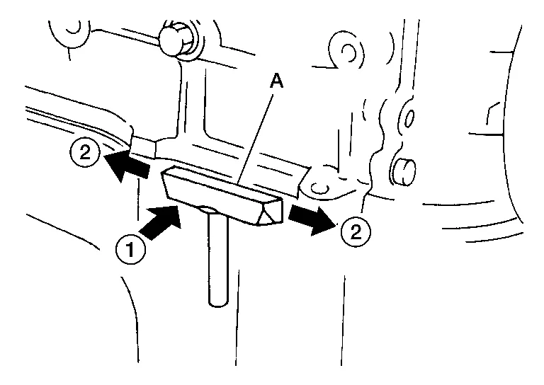
Tool number (A) : KV10111100 (J-37228) CAUTION:
Do not damage the mating surfaces.
-
Tap the seal cutter to insert it (1).
-
In areas where the Tool is difficult to use, lightly tap to slide it (2).
Remove O-rings (1) from cylinder block.
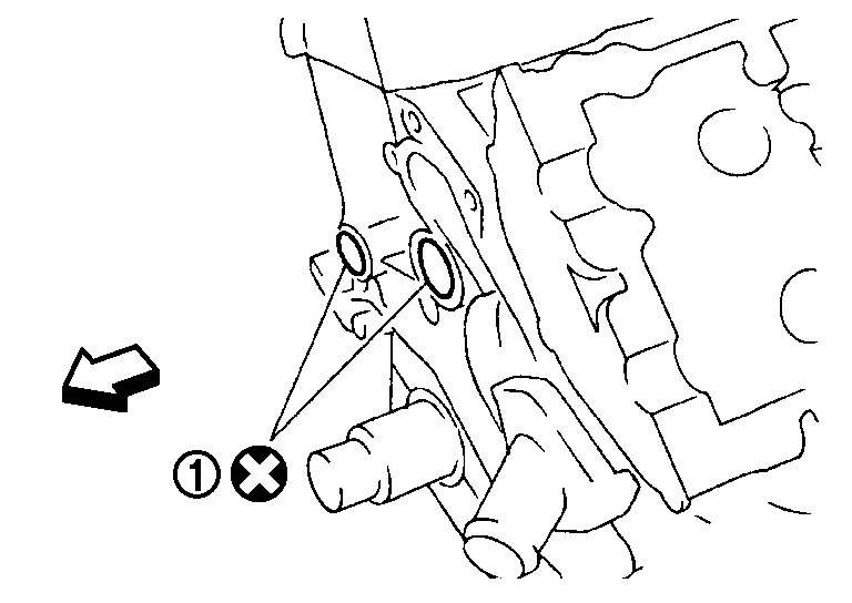
| : Engine front |
CAUTION:
Do not reuse O-rings.
Use a scraper to remove all of the old Silicone RTV Sealant from the front and rear timing chain case and opposite mating surfaces.
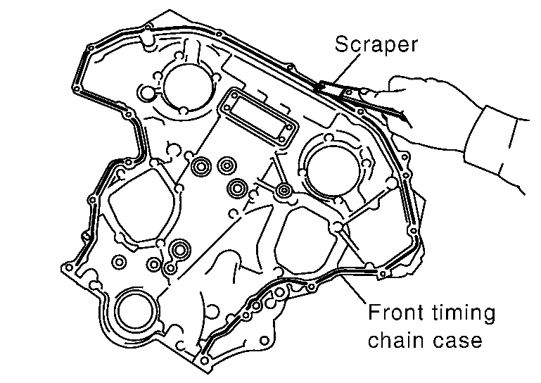
CAUTION:
Do not damage the mating surfaces.
Remove all old Silicone RTV Sealant from all the bolt holes and bolts.
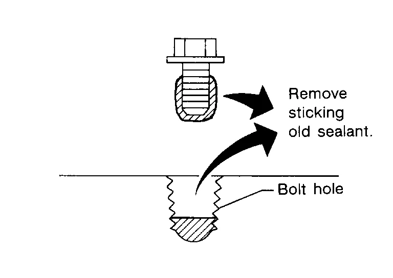
CAUTION:
Do not damage the threads or mating surfaces.
INSTALLATION
Install O-rings (1) on cylinder block.
| : Engine front |
CAUTION:
Do not reuse O-rings.
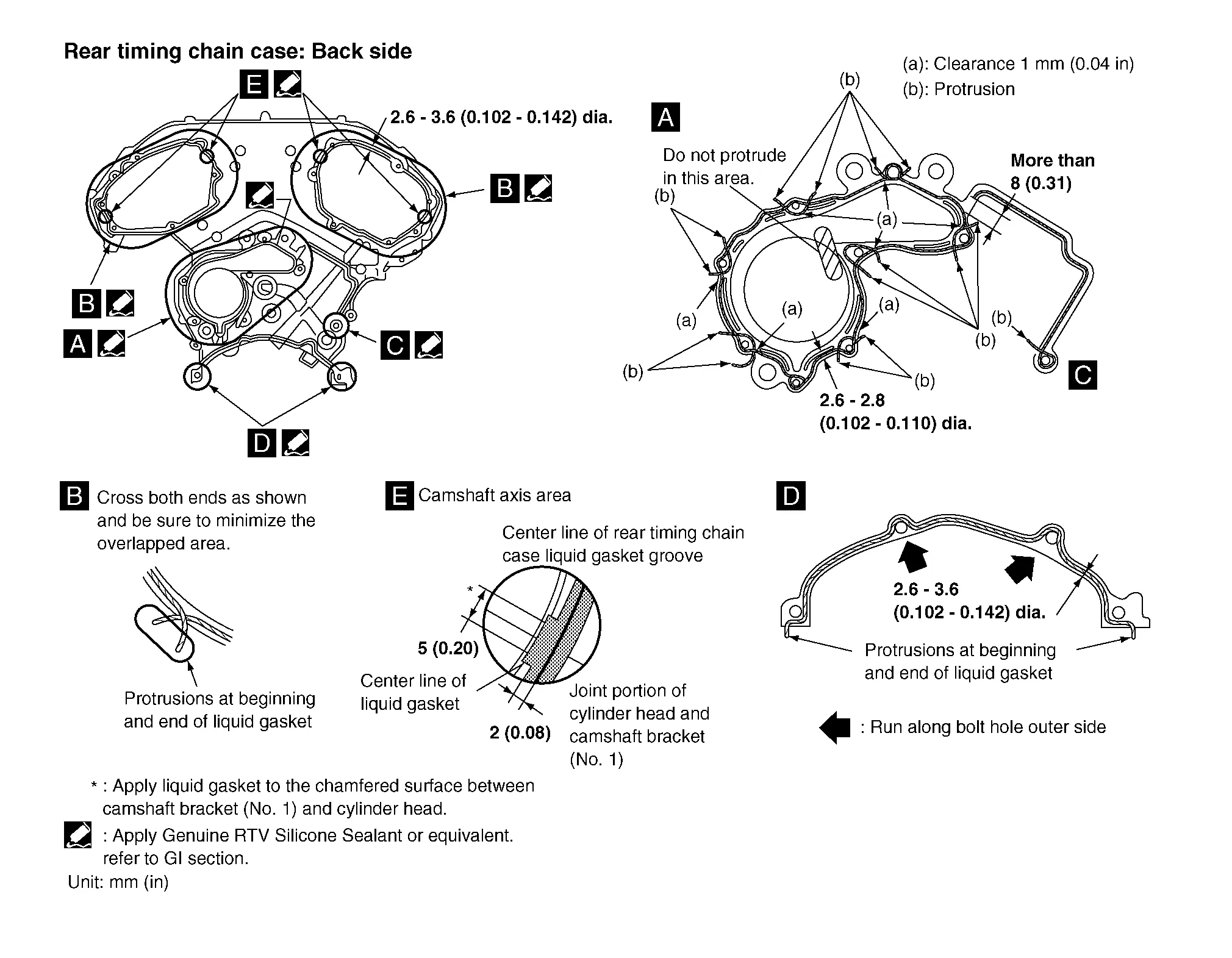
Apply Genuine Silicone RTV Sealant or equivalent, to the rear timing chain case using suitable tool as shown. Refer to Recommended Chemical Products and Sealants.
CAUTION:
-
Installation should be done within 5 minutes after applying liquid gasket.
-
Do not fill the engine with engine oil for at least 30 minutes after the components are installed to allow the sealant to cure.
-
Wipe off liquid gasket where it touches the engine coolant passage at point (A).
-
Follow the installation instructions for applying the liquid gasket. Pay particular attention to the water pump and cylinder area.
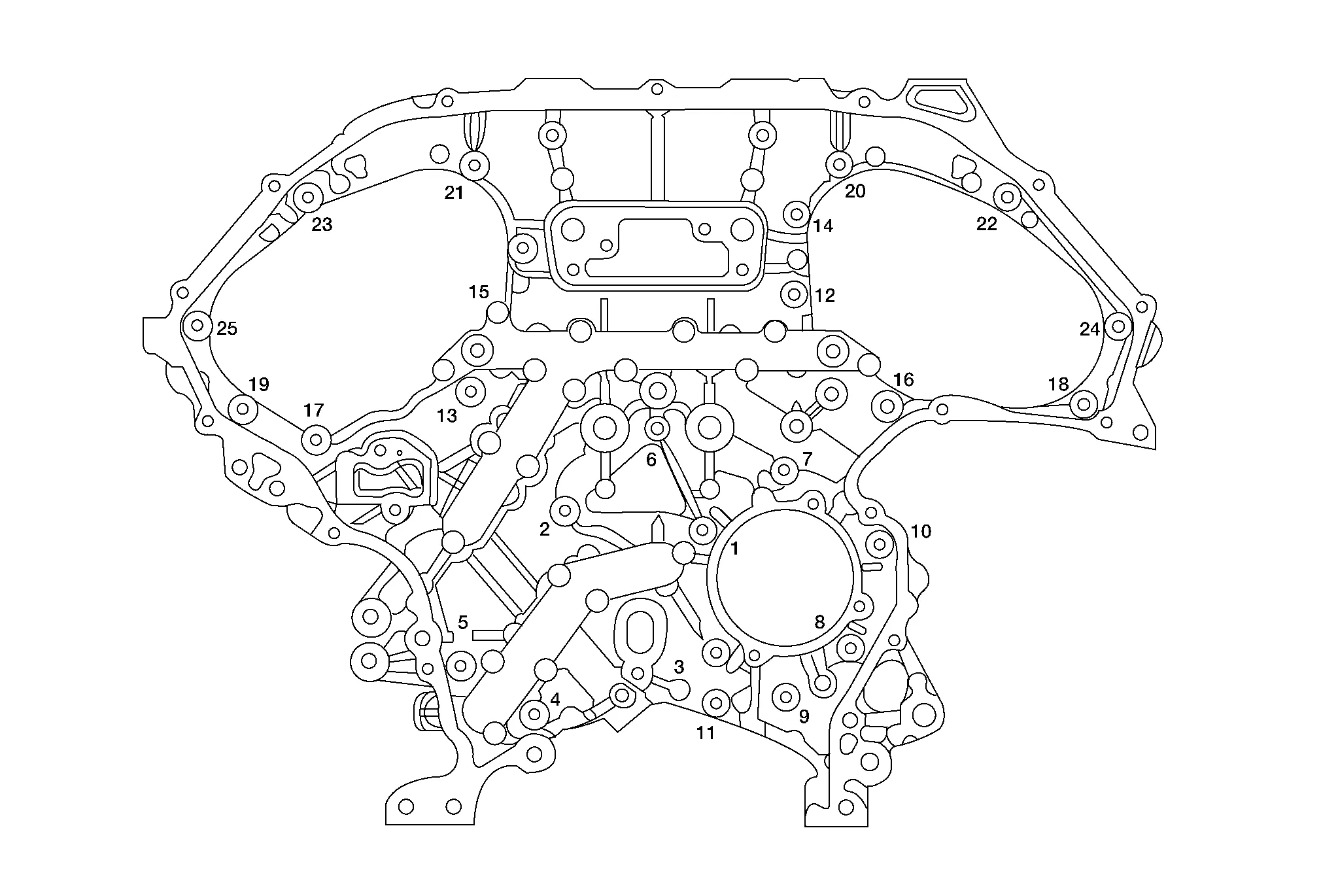
Align the rear timing chain case and water pump assembly with the dowel pins (RH and LH) on the cylinder block and install the case. Make sure the O-rings stay in place during installation.Tighten the bolts in the numerical order as shown. There are two bolt lengths used. Follow the chart below for proper bolt length specifications.
| Bolt length | Bolt position | Torque specification |
| 20 mm (0.79 in) | 1, 2, 3, 6, 7, 8, 9, 10 | 12.7 N·m (1.3 kg-m, 9 ft-lb) |
| 16 mm (0.63 in) | All except the above | 12.7 N·m (1.3 kg-m, 9 ft-lb) |
 NOTE:
NOTE:
If liquid gasket protrudes, wipe it off immediately.
Install the timing chains (primary and secondary). Refer to Removal and Installation.
Install the front timing chain case. Refer to Removal and Installation.
Install the upper oil pan. Refer to Removal and Installation (Upper Oil Pan).
Install the engine assembly. Refer to Removal and Installation (FWD) or Removal and Installation (AWD).
 Timing Chain
Exploded View
1.
Timing chain tensioner (secondary) (bank 2)
2.
Internal chain guide
3.
Timing chain tensioner (secondary) (bank 1)
4.
Camshaft sprocket (bank 1) (EXH)
5...
 Camshaft
Exploded View
1.
Camshaft position sensor bracket (bank 1)
2.
Camshaft brackets
3.
No. 1 camshaft bracket (bank 1)
4.
Camshaft (EXH) (bank 1)
5...
Other information:
Nissan Murano (Z52) 2015-2024 Service Manual: Battery Terminal with Fusible Link
Exploded View 1. Cover 2. Positive terminal 3. Battery 4. Harness connectors 5. Fusible link box (battery) 6. Positive cable Front Removal and Installation REMOVALDisconnect negative battery terminal. CAUTION: To prevent damage to the parts, disconnect the negative terminal from the battery negative post first...
Nissan Murano (Z52) 2015-2024 Service Manual: System
System Description SYSTEM DIAGRAMADAS CONTROL UNIT INPUT/OUTPUT SIGNAL ITEMInput Signal Item Transmit unit Signal name Description ECM CAN communication Closed throttle position signal Receives idle position state (ON/OFF) Accelerator pedal position signal Receives accelerator pedal position (angle) Engine speed signal Receives engine speed Stop lamp switch signal Receives an operational state of the brake pedal Brake pedal position switch signal Receives an operational state of the brake pedal TCM CAN communication Input speed signal Receives the number of revolutions of input shaft Current gear position signal Receives a current gear position Shift position signal Receives a selector lever position Output shaft revolution signal Receives the number of revolutions of output shaft ABS actuator and electric unit (control unit) CAN communication ABS malfunction signal Receives a malfunction state of ABS ABS operation signal Receives an operational state of ABS ABS warning lamp signal Receives an ON/OFF state of ABS warning lamp TCS malfunction signal Receives a malfunction state of TCS TCS operation signal Receives an operational state of TCS VDC OFF switch signal Receives an ON/OFF state of VDC VDC malfunction signal Receives a malfunction state of VDC VDC operation signal Receives an operational state of VDC Nissan Murano Vehicle speed signal (ABS) Receives wheel speeds of four wheels Yaw rate signal Receives yaw rate acting on the Nissan Murano vehicle Stop lamp switch signal Receives an operational state of the brake pedal Steering angle sensor CAN communication Steering angle sensor malfunction signal Receives a malfunction state of steering angle sensor Steering angle sensor signal Receives the number of revolutions, turning direction of the steering wheel Steering angle speed signal Receives the turning angle speed of the steering wheel Distance sensor ITS communication Distance sensor signal Receives detection results, such as the presence or absence of a leading Nissan Murano vehicle and distance from the vehicle Lane camera unit Chassis CAN communication Pedestrian ahead signal Receives detection results of pedestrian ahead of Nissan Murano vehicle Vehicle ahead signal Receives detection results of Nissan Murano vehicle ahead Output Signal Item Reception unit Signal name Description ABS actuator and electric unit (control unit) CAN communication Brake fluid pressure control signal Transmits a brake fluid pressure control signal to activates the brake Combination meter CAN communication Meter display signal Nissan Murano Vehicle ahead detection indicator signal Transmits a signal to display a state of the system on the information display AEB/I-FCW system display signal AEB warning signal Distance sensor ITS communication Nissan Murano Vehicle speed signal Transmits a vehicle speed calculated by the ADAS control unit Steering angle sensor signal Transmits a steering angle sensor signal received from the steering angle sensor Warning buzzer Warning buzzer signal Activates the warning buzzer ICC brake hold relay ICC brake hold relay drive signal Activates the brake hold relay and turns ON the stop lamp DESCRIPTION Automatic Emergency Braking (AEB) system can assist the driver when there is a forward collision with the Nissan Murano vehicle ahead in the traveling lane...
Categories
- Manuals Home
- Nissan Murano Owners Manual
- Nissan Murano Service Manual
- Turning the AEB system on/off
- How to enable/disable the LDW system
- Vehicle Dynamic Control (VDC) OFF switch
- New on site
- Most important about car
Driver and passenger supplemental knee air bag

Driver’s side
The knee air bag is located in the knee bolster, on the driver’s and passenger’s side. All of the information, cautions and warnings in this manual apply and must be followed. The knee air bag is designed to inflate in higher severity frontal collisions, although it may inflate if the forces in another type of collision are similar to those of a higher severity frontal impact. It may not inflate in certain collisions.

Passenger’s side