Nissan Murano: Engine Mechanical :: Removal and Installation / Timing Chain
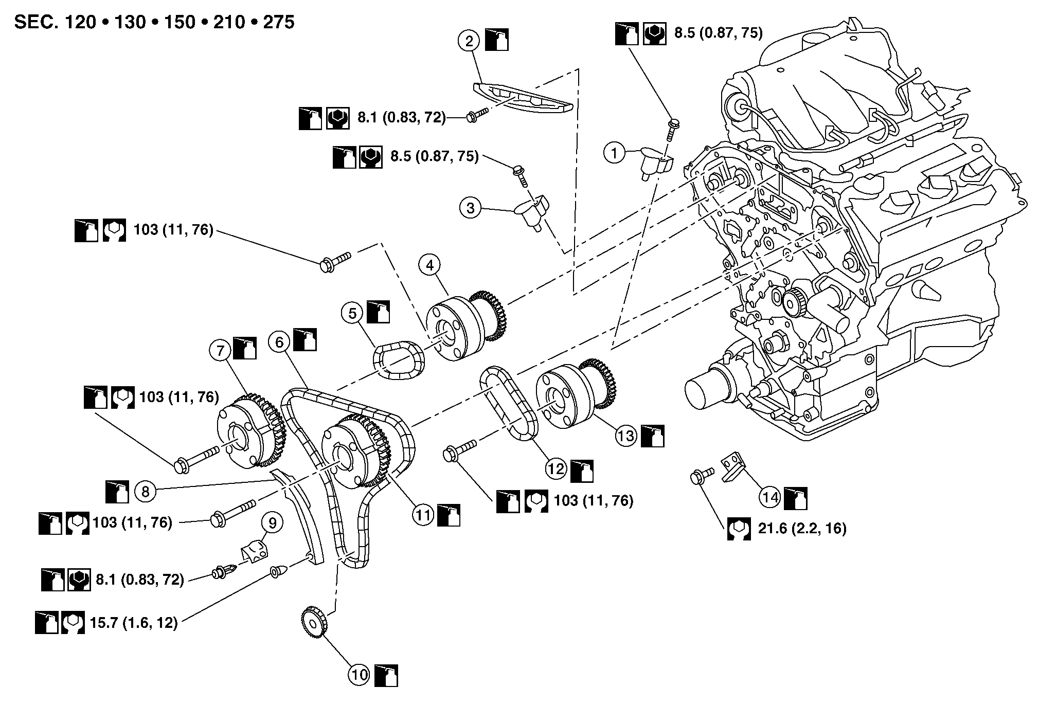
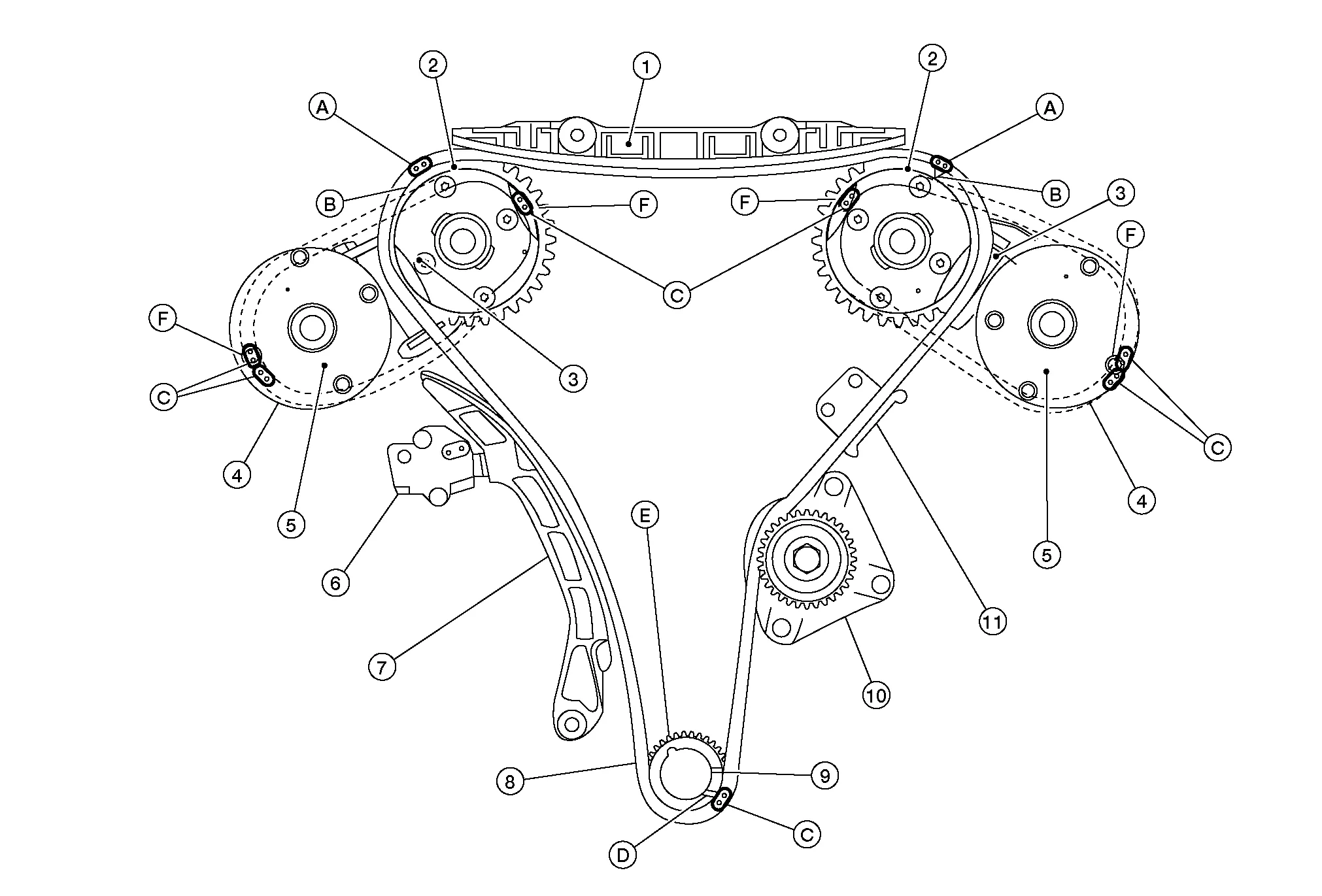
| 1. | Timing chain tensioner (secondary) (bank 2) | 2. | Internal chain guide | 3. | Timing chain tensioner (secondary) (bank 1) |
| 4. | Camshaft sprocket (bank 1) (EXH) | 5. | Timing chain (secondary) | 6. | Timing chain (primary) |
| 7. | Camshaft sprocket (bank 1) (INT) | 8. | Slack guide | 9. | Timing chain tensioner (primary) |
| 10. | Crankshaft sprocket | 11. | Camshaft sprocket (bank 2) (INT) | 12. | Timing chain (secondary) |
| 13. | Camshaft sprocket (bank 2) (EXH) | 14. | Tension guide |
CAUTION:
-
After removing timing chains, do not turn the crankshaft and camshaft separately or the valves will strike the pistons.
-
When installing camshafts, chain tensioners, oil seals, or other sliding parts, lubricate contacting surfaces with new engine oil.
-
Apply new engine oil to bolt threads and seat surfaces when installing camshaft sprockets, camshaft brackets, and crankshaft pulley.
REMOVAL
Remove front timing chain case. Refer to Removal and Installation.
Remove the intake manifold collector. Refer to Removal and Installation.
Remove the spark plugs. Refer to Removal and Installation.
Place paint marks on the timing chain and sprockets to indicate the correct position of the components for installation.
Disconnect the camshaft position sensor harness connectors.
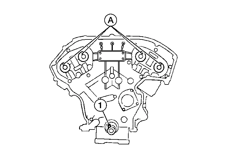
Remove the timing chain tensioner (primary).Pull lever down and release plunger stopper tab (A). Plunger stopper tab can be pushed up to release (coaxial structure with lever).
| (B) | : Timing chain tensioner (primary) |
| (C) | : Stopper pin |
| (D) | : Lever |
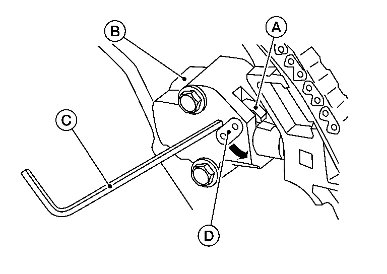
| (C) | : Installation bolts |
Remove internal chain guide (1), tension guide (3) and slack guide (2).
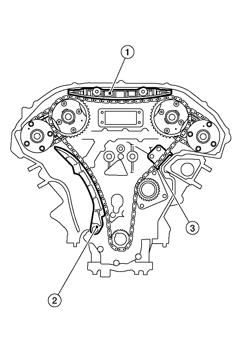
 NOTE:
NOTE:
Tension guide (3) can be removed after removing timing chain (primary).
Remove timing chain (primary) and crankshaft sprocket.
CAUTION:
After removing timing chains, do not turn the crankshaft and camshaft separately or the valves will strike the pistons.
Remove timing chain (secondary) and camshaft sprockets as follows:Insert a suitable stopper pin into the hole (C) on the bank 1 (B) and bank 2 (A) timing chain tensioners [secondary (1)].
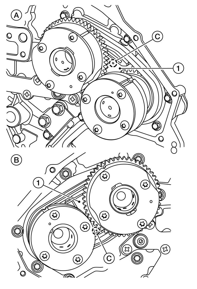
NOTE:
-
Use approximately 0.5 mm (0.02 in) diameter hard metal pin as a stopper pin.
-
Removal of camshaft bracket (No. 1) is required prior to removing the timing chain tensioner [secondary (1)].
-
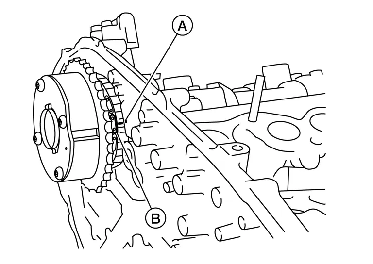
Secure the hexagonal portion of camshaft using a suitable tool (A) and loosen bolts with suitable tool (B).
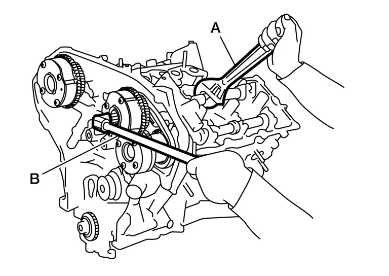
CAUTION:
Do not loosen bolts using anything other than the camshaft hexagonal portion. Do not apply tension to the timing chain.
-
Turn camshaft slightly to keep the chain tight when removing the timing chain (secondary).
-
Insert 0.5 mm (0.020 in) thick metal or resin plate between timing chain and timing chain tensioner plunger [guide (E)]. Remove timing chain [secondary (2)] together with camshaft sprockets with timing chain loose from guide groove.
(1) : Timing chain tensioner (secondary) (A) : Bank 1 (RH) (B) : View B (C) : Stopper pin (D) : Plate (F) : Timing chain tensioner (body) CAUTION:
Be careful of plunger coming off when removing timing chain (secondary). The plunger of timing chain tensioner (secondary) moves during operation, which could cause the stopper pin to fall out.
CAUTION:
-
Handle camshaft sprocket (INT) carefully to avoid any shock to camshaft sprocket.
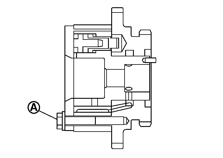
-
Do not disassemble. [Do not loosen bolts (A) as shown].
INSPECTION
Check for cracks and any excessive wear of the timing chain. Replace the timing chain as necessary.
INSTALLATION
| 1. | Internal chain guide | 2. | Camshaft sprocket (INT) | 3. | Timing chain tensioner (secondary) |
| 4. | Timing chain (secondary) | 5. | Camshaft sprocket (EXH) | 6. | Timing chain tensioner (primary) |
| 7. | Slack guide | 8. | Timing chain (primary) | 9. | Crankshaft sprocket |
| 10. | Water pump | 11. | Tension guide | A. | Mating mark (green link) |
| B. | Mating mark (punched) | C. | Mating mark (orange link) | D. | Mating mark (notched) |
| E. | Crankshaft keyway | F. | Mating mark (back side) |
NOTE:
This illustration shows the relationship between the mating mark on each timing chain and on the corresponding sprocket with the components installed.
Install timing chain tensioners (secondary) with a new O-ring and the stopper pin attached.
CAUTION:
Do not reuse O-ring.
Check that dowel pin (A) and crankshaft key (1) are located as shown. (No. 1 cylinder at compression TDC)
NOTE:
Though camshaft does not stop at the position as shown, for the placement of cam nose, it is generally accepted camshaft is placed in the same direction.
| Camshaft dowel pin | |
| : At cylinder head upper face side in each bank | |
| Crankshaft key | |
| : At cylinder head side of bank 1 | |
Install timing chain (secondary) and camshaft sprockets (INT and EXH) as follows:
CAUTION:
Mating marks between timing chain and sprockets slip easily. Confirm all mating mark positions repeatedly during the installation process.
Push plunger of timing chain tensioner (secondary) and keep it pressed in with stopper pin (A).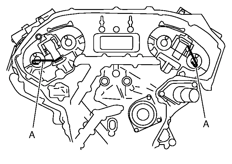
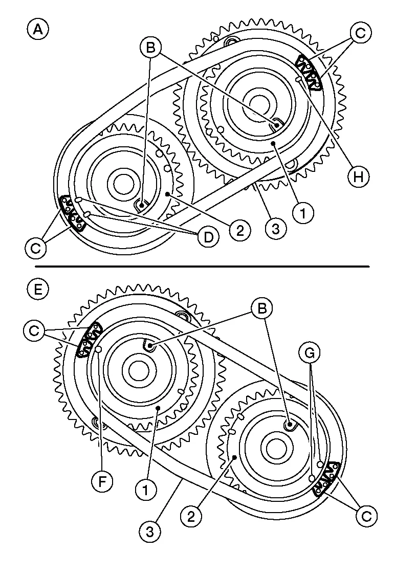
| (A) | : Bank 2 |
| (B) | : Dowel pin hole |
| (C) | : Orange links |
| (D) | : Mating mark (2 oblongs) |
| (E) | : Bank 1 |
| (F) | : Mating mark (Circle) |
| (G) | : Mating mark (2 circles on front face) |
| (H) | : Mating mark (Oblong) |
NOTE:
Bank 1 and Bank 2 shown (rear view).
-
Align the mating marks on timing chain [secondary (orange link)] with the ones on camshaft sprockets [INT and EXH (punched)], and install them.
-
Mating marks for camshaft sprocket (INT) are on the back side of camshaft sprocket (secondary).
-
There are two types of mating mark, circle and oblong types. They should be used for the bank 1 and bank 2, respectively.
Bank 1 : Use circle type. Bank 2 : Use oblong type. -
Align dowel pin on camshafts with the groove on sprockets, and install them.
-
Tighten the bolts for the camshaft sprockets by hand enough to prevent the dowel pins from falling out of the grooves.
-
It may be difficult to visually check the dislocation of mating marks during and after installation. To make the matching easier, make a mating mark (A) on the top of sprocket teeth and its extended line with paint.
(B) : Mating mark (orange link)
After confirming the mating marks are aligned, tighten the camshaft sprocket bolts using suitable tool (B).
-
Secure the camshaft using a suitable tool (A) at the hexagonal portion to tighten the bolts.
Remove suitable stopper pins from hole (C) in timing chain tensioners [secondary (1)].
| (A) | : Bank 1 (RH) |
| (C) | : Bank 2 (LH) |
Install the crankshaft sprocket (C) on the crankshaft.
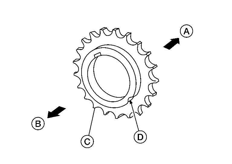
-
Make sure the mating marks (D) on the crankshaft sprocket (C) face the front of the engine (B).
-
The flat side of the crankshaft sprocket (C) is on the crankshaft side (A)
Install the timing chain (primary).
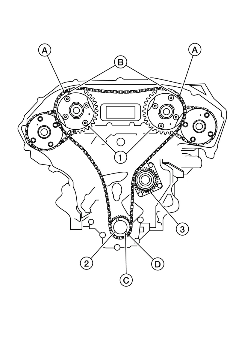
-
Install timing chain (primary) so the mating mark (punched) (B) on camshaft sprocket (1) is aligned with the green link (A) on the timing chain, while the mating mark (notched) (C) on the crankshaft sprocket (2) is aligned with the orange link (D) on the timing chain, as shown.
-
When it is difficult to align mating marks of the timing chain (primary) with each sprocket, gradually turn the camshaft using a wrench on the hexagonal portion to align it with the mating marks.
-
During alignment, be careful to prevent dislocation of mating mark alignments of the secondary timing chains.
| (3) | : Water pump |
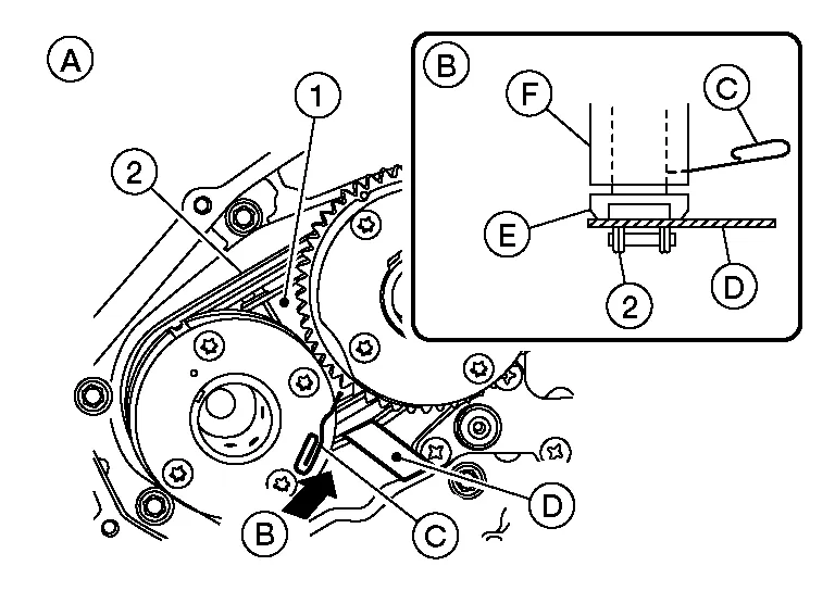
Install the internal chain guide (1) and slack guide (2).
| (3) | : Tension guide |
CAUTION:
Do not over tighten slack guide bolt (2). It is normal for a gap (A) to exist under the bolt seat when bolt is tightened to specification.

| (1) | : Slack guide |
| (3) | : Cylinder block |
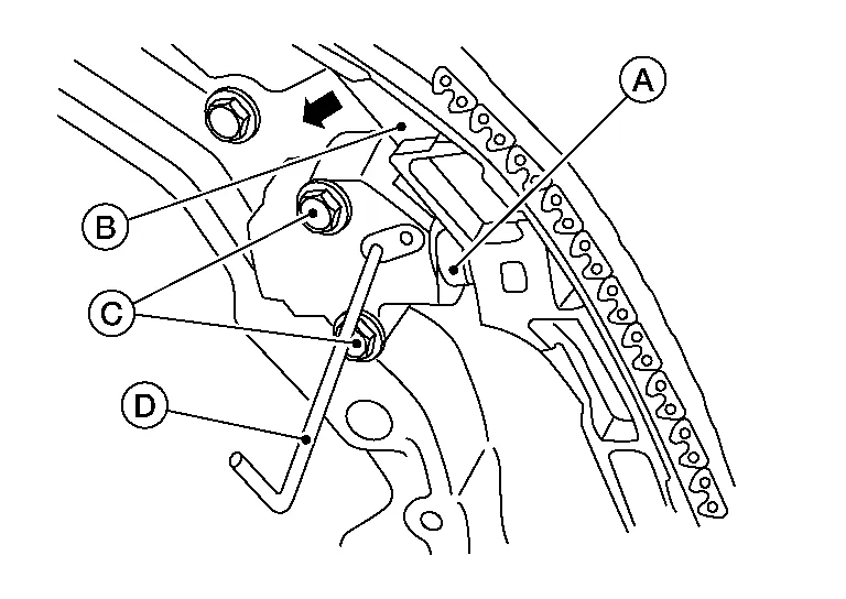
Install the timing chain tensioner (primary) with the following procedure:Pull plunger stopper tab (A) up (or turn lever downward) so as to remove plunger stopper tab from the ratchet of plunger (D).
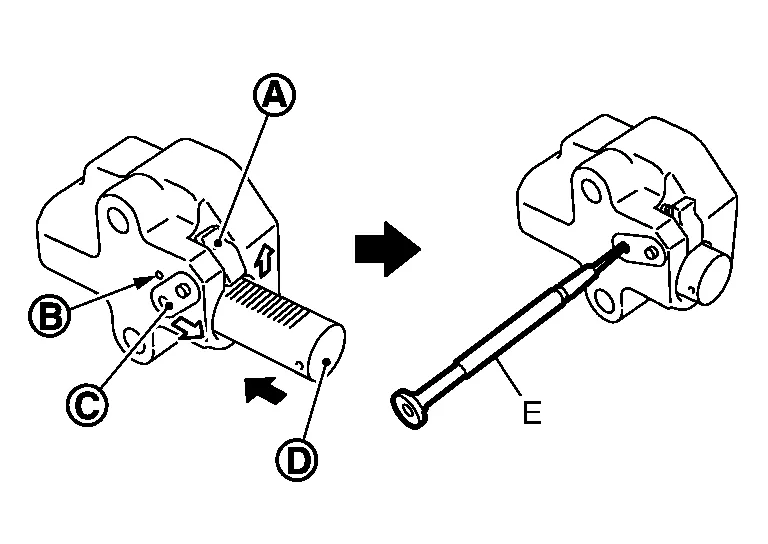
NOTE:
Plunger stopper tab and lever (C) are synchronized.
Push plunger into the inside of tensioner body. Hold plunger in the fully compressed position by engaging plunger stopper tab with the tip of ratchet. To secure lever, insert stopper pin (E) through hole of lever into tensioner body hole (B).-
The lever parts and the tab are synchronized. Therefore, the plunger will be secured under this condition.
NOTE:
Illustration shows the example of 1.2 mm (0.047 in) diameter thin screwdriver being used as the stopper pin.
Install timing chain tensioner (primary) (1).
-
Remove any dirt and foreign materials completely from the back and the mounting surfaces of timing chain tensioner (primary).
Reconfirm that the matching marks on the sprockets and the timing chain have not slipped out of alignment.
Install the spark plugs. Refer to Removal and Installation.
Install the intake manifold collector. Refer to Removal and Installation.
Install the front timing chain case. Refer to Removal and Installation.
 Front Timing Chain Case
Exploded View
1.
Engine assembly
2.
Front timing chain case oil filter
3.
Water pump cover
4.
Crankshaft pulley
5.
Front oil seal
6...
 Rear Timing Chain Case
Exploded View
1.
O-ring
2.
Blind plug (if equipped)
3.
Rear timing chain case
4.
Cylinder block
5.
O-ring
6.
O-ring
A.
Refer to Removal and Installation...
Other information:
Nissan Murano (Z52) 2015-2024 Owners Manual: Anti-lock Braking System (ABS)
WARNING The ABS is a sophisticated device, but it cannot prevent accidents resulting from careless or dangerous driving techniques. It can help maintain vehicle control during braking on slippery surfaces. Remember that stopping distances on slippery surfaces will be longer than on normal surfaces even with ABS...
Nissan Murano (Z52) 2015-2024 Owners Manual: Flat towing for front wheel drive vehicle (if so equipped)
Towing your vehicle with all four wheels on the ground is sometimes called flat towing. This method is sometimes used when towing a vehicle behind a recreational vehicle, such as a motor home. CAUTION Failure to follow these guidelines can result in severe transmission damage...
Categories
- Manuals Home
- Nissan Murano Owners Manual
- Nissan Murano Service Manual
- Settings
- Vehicle Dynamic Control (VDC) OFF switch
- How to enable/disable the LDW system
- New on site
- Most important about car
Front manual seat adjustment (if so equipped)
Your vehicle seats can be adjusted manually. For additional information about adjusting the seats, refer to the steps outlined in this section.
Forward and backward
