Nissan Murano: Power Outlet :: Removal and Installation / Power Socket
FRONT CONSOLE POWER SOCKET or REAR CARGO POWER SOCKET
 NOTE:
NOTE:
If unable to use the Tool because of power socket location or access to the harness connector, then further removal of interior components may be required. Refer to Exploded View (Front Console Power Socket) or Removal and Installation (Rear Cargo Power Socket).
Removal
Remove the fuse for the power socket.
Insert one side of the Tool (A) into one of the square holes inside the power socket.
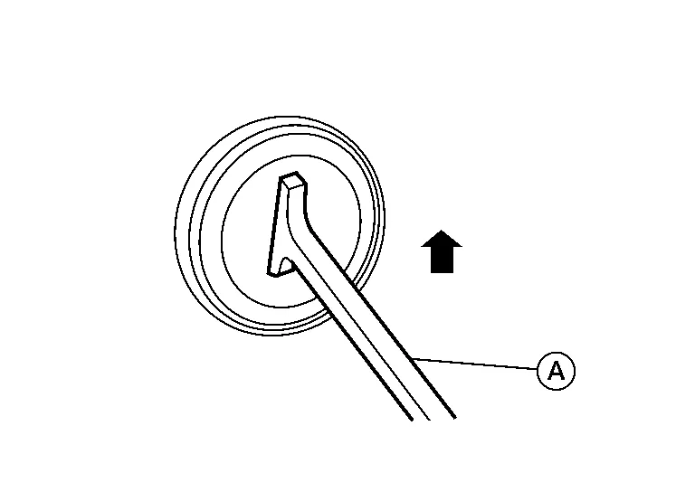
| Tool number | : — (J-42059) |
Lift up the handle of the Tool until the other side snaps into the other square hole in the power socket.
Pull the power socket straight out with the Tool.
Disconnect the harness connector from the power socket.

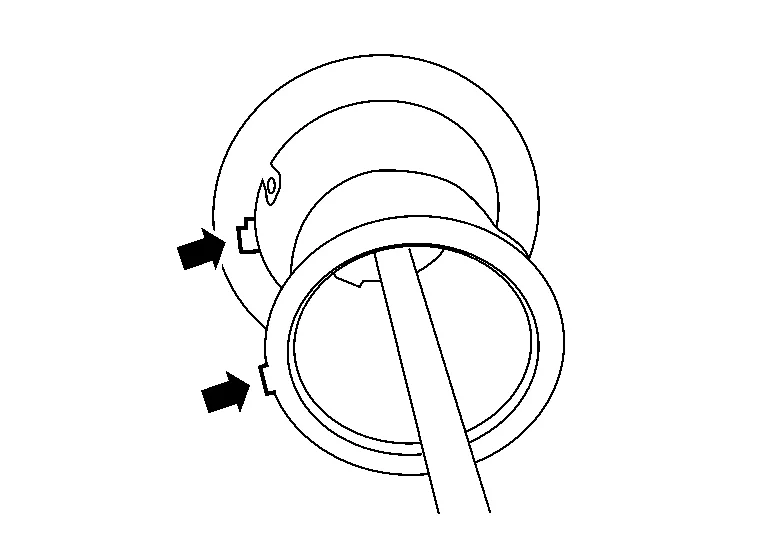
Remove the ring from the power socket finisher while pressing the pawls.
Installation
Installation is in the reverse order of removal.
NOTE:
Make sure to align the tab with the square notched area during installation.

 Rear Usb Charge Port
Removal and Installation
REMOVALRemove center console rear finisher. Refer to Exploded View.
Using a suitable tool, release pawls and remove rear USB charge port (1) from center console rear finisher (2)...
Other information:
Nissan Murano (Z52) 2015-2024 Service Manual: Steering Gear and Linkage
Inspection BOOTCheck boot for cracks. Replace if any damage is found.OUTER SOCKET AND INNER SOCKET Ball joint swinging torque Hook the Tool at the measuring point and pull the Tool. Make sure that the Tool reads the specified value when ball stud and inner socket start to move...
Nissan Murano (Z52) 2015-2024 Service Manual: Ecm, Ipdm E/r, Bcm
L..
Categories
- Manuals Home
- Nissan Murano Owners Manual
- Nissan Murano Service Manual
- Checking engine oil level
- Turning the AEB system on/off
- Fuel recommendation
- New on site
- Most important about car
Unfastening the seat belts. Checking seat belt operation
Unfastening the seat belts

To unfasten the seat belt, press the button
on the buckle  . The seat belt
automatically
retracts.
. The seat belt
automatically
retracts.