Nissan Murano: Repairing Procedures and Precautions / Partial Replacement of Panel (welded Panel)
If damage occurs in a welded panel, it can be entirely replaced by a service panel or partial replacement can be done by cutting and replacing damaged portion with a service panel.
 NOTE:
NOTE:
When welding and dressing the parts, cover up holes of these parts with tape to prevent debris from entering.
-
Assembly panel replacement or partial panel replacement
Assembly panel replacement means replacement of a complete panel by cutting all the welded portions.
Partial panel replacement is a method by which only the damaged portion of a panel is replaced. Partial panel replacement can be used when assembly panel replacement is too costly and time consuming, and when the damage is localized.
-
Cutting positions for partial replacement
The illustration is just example, please see each Body Repair Manual for details.
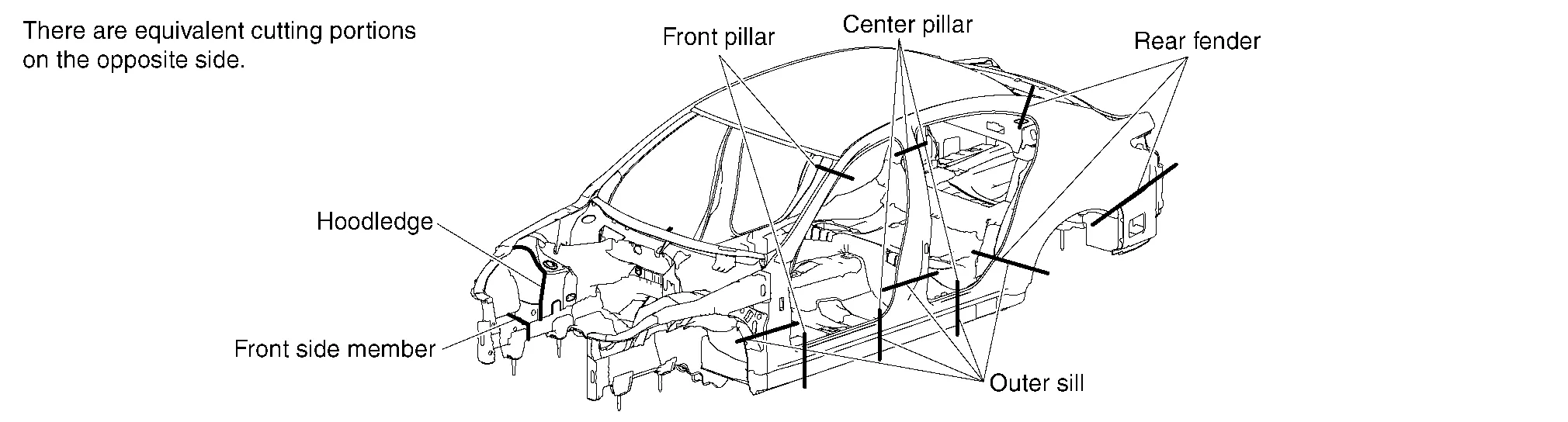
Cutting panels for partial replacement is not allowed on some portions. If panels are cut in improper portions, body strength cannot be maintained. The allowable positions vary with body structure, panel strength or shape and differ from model to model. They are indicated in the Body Repair Manual of each model. In principle, the following portions may be cut:
-
Portions without reinforcement or ducting
-
Portions where no stress concentration occurs
-
Portions with small finish area where finishing can be easily accomplished (where the connected portions can be covered by garnish or moulding)
-
Portions where work area or disassembling of parts is minimized
Most body panels are joined by spot welding. It is difficult to cut them at the welded portion.
To shorten work time, pull the damaged portion roughly, them cut near the panel joint in advance so that tools can be used properly to cut the spot welded portion. It is commonly used on panels having complicated structures.
Cutting body panel and service panels by leaving an overlap tolerance is also called rough cutting.
Use the cutting tools properly according to the portion to be cut, panel thickness, and panel structure.
Tools commonly used for this purpose and their features are described below:
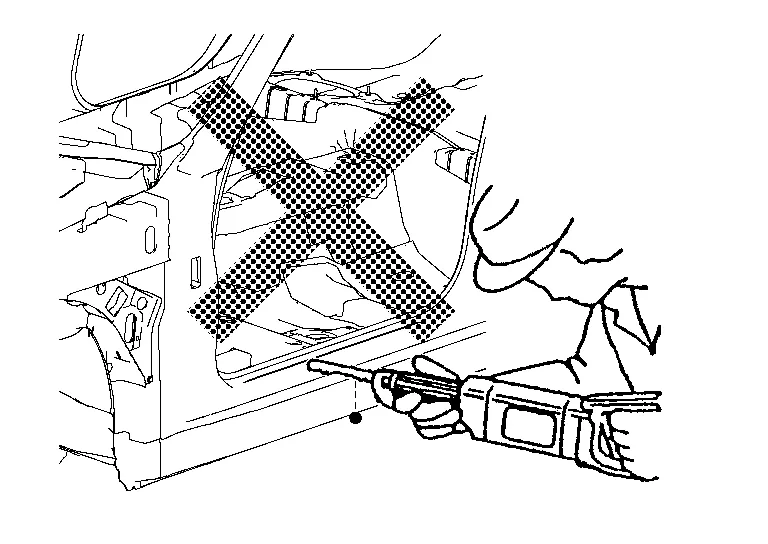
(1) ROUGH CUTTING USING AN AIR SAW
(a) Major application
Members and pillars including side member, cross member, rear pillar, etc..
(b) Features
Clear cut line. Suitable for cutting both thin and comparatively thick sheet metal.
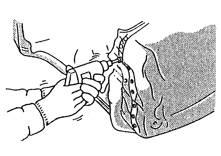
(2) ROUGH CUTTING USING AN AIR CHISEL
(a) Major application
Thin sheet metal including the rear fender and rear floor
(b) Features
Faster cutting speed
High noise level
Not applicable to thick sheet metal
Irregular cut line
Excessive sparking
(3) ROUGH CUTTING WITH AN OXY-ACETYLENE CUTTING TORCH
(a) Major application
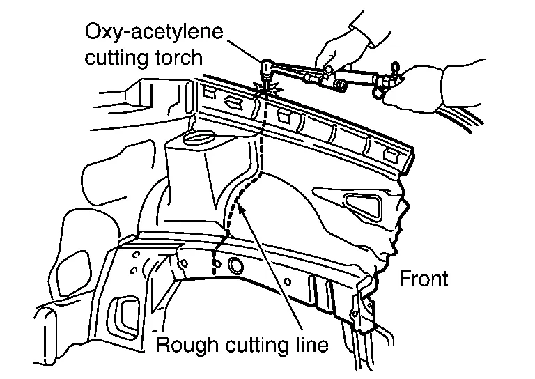
Thick sheet metal including side member, cross member, hoodledge, etc..
(b) Features
Faster cutting speed
A vehicle body is constructed by using three different welding methods [spot welding, MAG and brazing]. Cutting welded portion by these methods is described below.
Spot welding is generally used on two or more overlapped panels. The tool or cut off method must be changed according to whether the panel to be removed is on the top, in the middle or on the bottom.
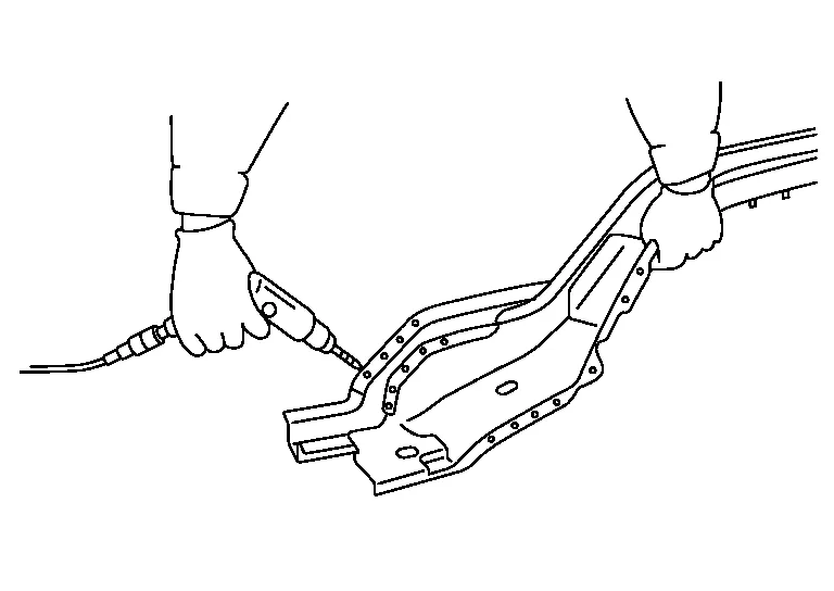
(1) CONFIRMING THE SPOT WELDED POSITION
Remove paint, undercoat, and sealer from the panel to confirm the spot welded positions.
(a) Using air sander, rotary wire brush, or file sanding belt:
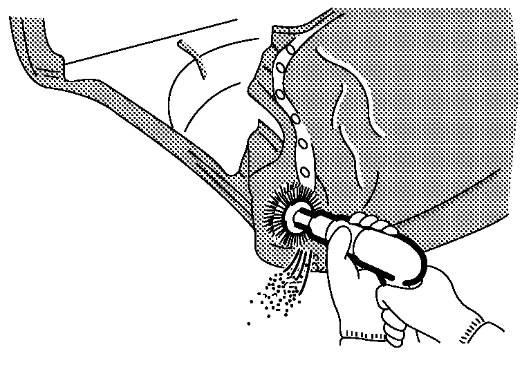
When using this method, do not grind too much of the panel. Sand or brush the panel while confirming the spot welded portion.
(b) Using a chisel:
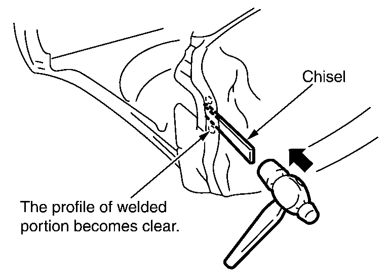
If the spot welded portion is indiscernible even after removing paint, insert the chisel blade between the panels and tap lightly with a hammer for confirmation.
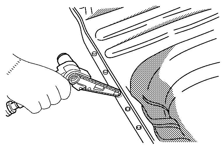
(2) CUTTING OFF SPOT WELDED PORTION
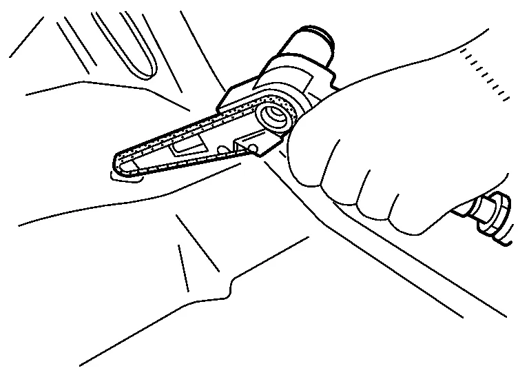
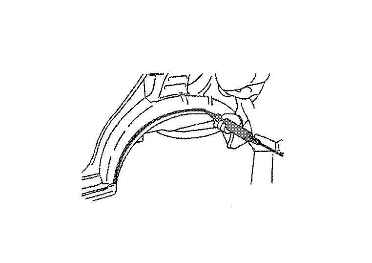
(a) Using a spot cutter:
There are two types of spot cutters (a drill type and a hole saw type). When using the spot cutter, be careful not to cut the lower panel.
|
|
|
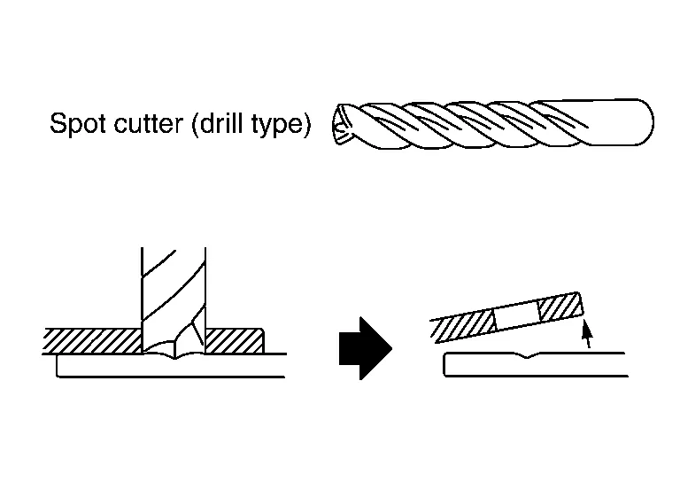
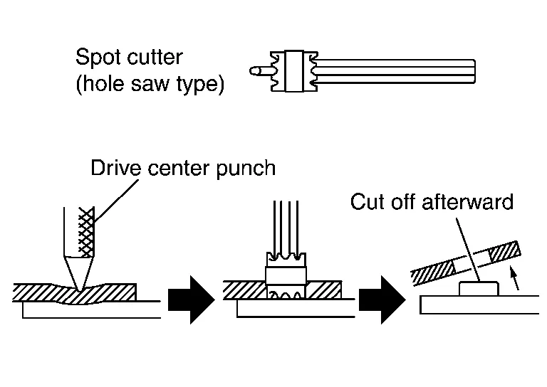
If it is difficult to weld from behind the lower panel, the spot cutter may be used to cut the spot welded portions without drilling the bottom panel.
The hole saw type spot cutter requires grinding of the spot weld after cutting. This requires additional work time.
(b) Using drill:
The drill may be used to cut welds from any portion welded by plug welding, by drilling out the plug welded portion.
|
|
|
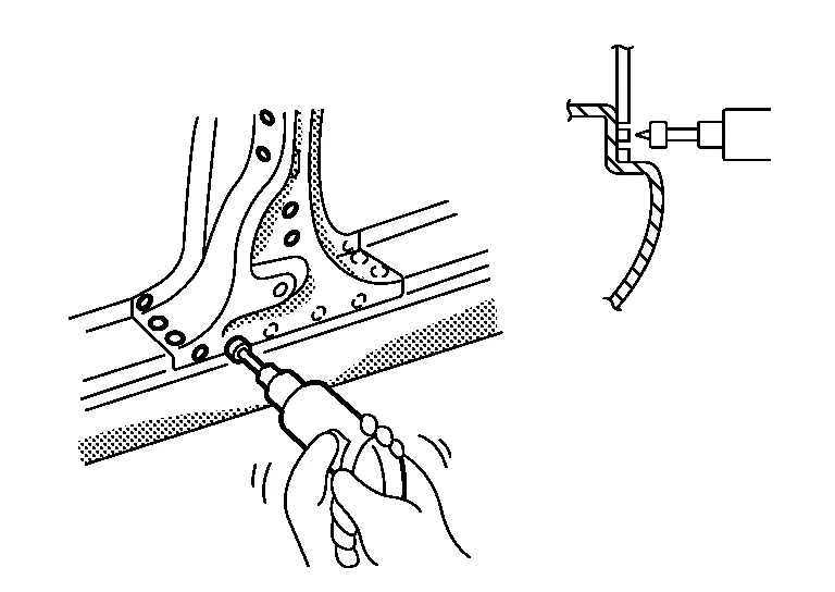
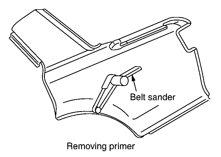
(3) CUTTING SPOT WELDED PORTIONS WITH AN AIR SANDER
If the spot cutter cannot be used, use the air sander (or belt sander) to cut off the spot welded portion. Use 3M File Belt Sander #33573 and Cubitron II File Belt Grade 60+ #33445 or equivalent.
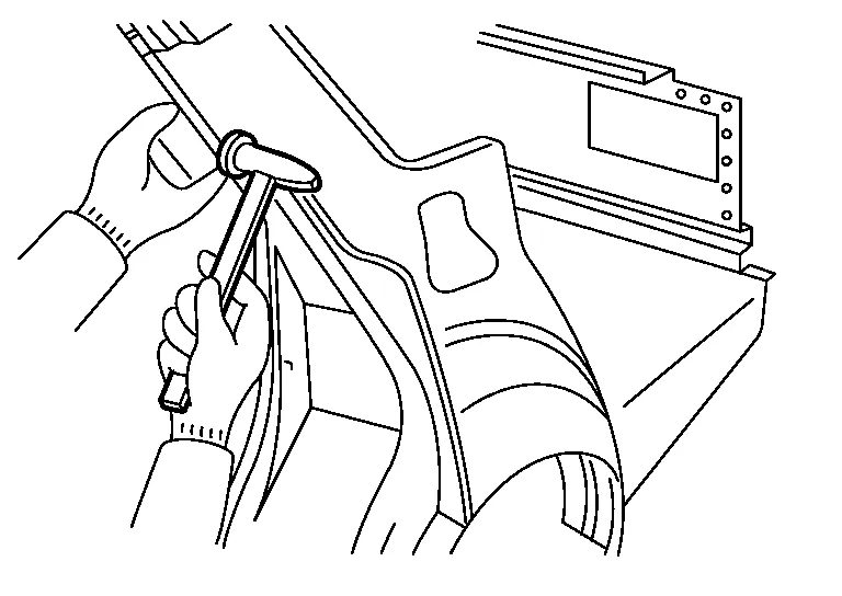
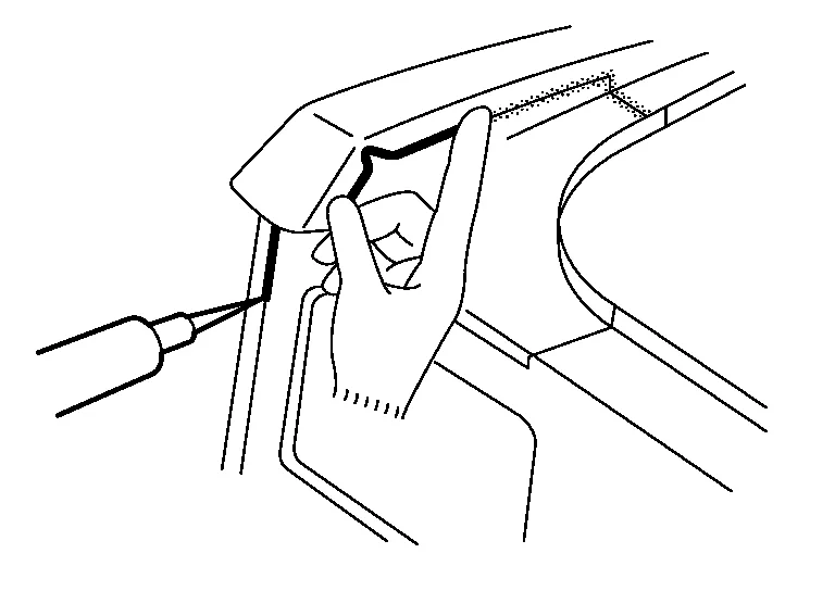
(4) REMOVING PANEL WITH A CHISEL
After cutting the spot welded portions, separate the panel using the chisel.
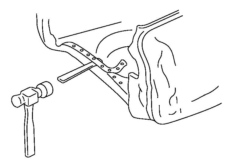
By doing this, spot welded portions will separate from their mating surfaces. Thus, work can proceed while confirming the separation of spot-welded portions.
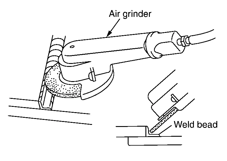
(5) CUTTING MAG WELDED PORTIONS
The MAG welding method is divided into two types (plug welding and seam welding). The plug weld portion can be cut off with a spot cutter or the like. To cut off the seam welded portion, grind the seam-weld bead with an air grinder to cut the welded portion. Be careful to grind from the replacement panel. Do not grind the reused panel excessively.
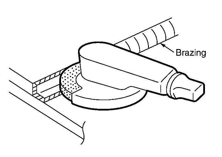
(6) CUTTING OFF BRAZED PORTION OF PANEL
Brazing is used to improve the external appearance of the joined portion (roof and fender) of the body outer panel as well as to improve sealing. Brazed portions can be generally disconnected by dissolving the braze with an oxy-acetylene torch.
If arc brazing was used, cut off the welded portion with an air sander or the like. The melting temperature of arc brazed metal is higher than that of ordinary brazing, and the panel may be damaged by this high temperature. Ordinary brazing and arc brazing may be discriminated by observing the color of the brazed metal. Ordinary brazing looks like a brass, while arc brazing has a copper color.
(a) Cutting with pneumatic saw and file belt sanding.
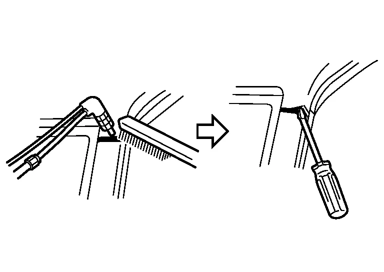
Remove the metal with a wire brush and separate the panel. While the filler metal is still hot, insert the tip of a screwdriver or the like between panels to prevent re-adhesion.
(b) Cutting with an air grinder use 3M 01991 weld grinding wheel (or equivalent)
Cut off the brazed portion with the air grinder. Do not grind excessively the panel to be reused.
High strength steel (HSS) means the steel from 440 MPa - 979 MPa.
Ultra high strength steel (UHSS) means the steel above 980 MPa.
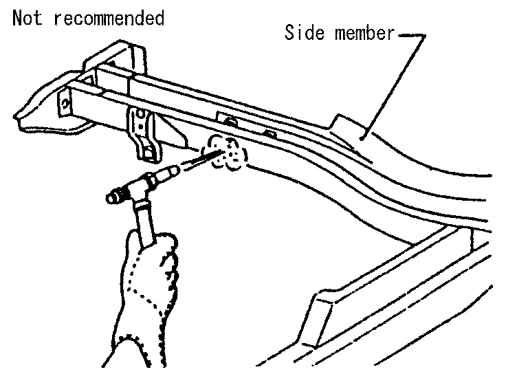
(a) The repair of reinforcements (such as side members) by heating is not recommended since it may weaken the component. When heating is unavoidable, do not heat HSS parts above 550°C (1,022°F). Verify heating temperature with a thermometer. (Crayon-type and other similar type thermometer are appropriate.)
When you heat the HSS or UHSS parts above 550°C (1,022°F), it must be replaced with new parts.
(b) When straightening body panels, use caution in pulling any HSS panel. Because HSS is very strong, pulling may cause deformation in adjacent portions of the body. In this case, increase the number of measuring points, and carefully pull the HSS panel.

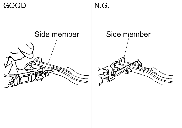
(c) When cutting HSS panels, avoid gas (torch) cutting if possible. Instead, use a saw to avoid weakening surrounding areas due to heat. If gas (torch) cutting is unavoidable, allow a minimum margin of 50 mm (1.97 in).
(d) When welding HSS panels, use spot welding whenever possible in order to minimize weakening surrounding areas due to heat.
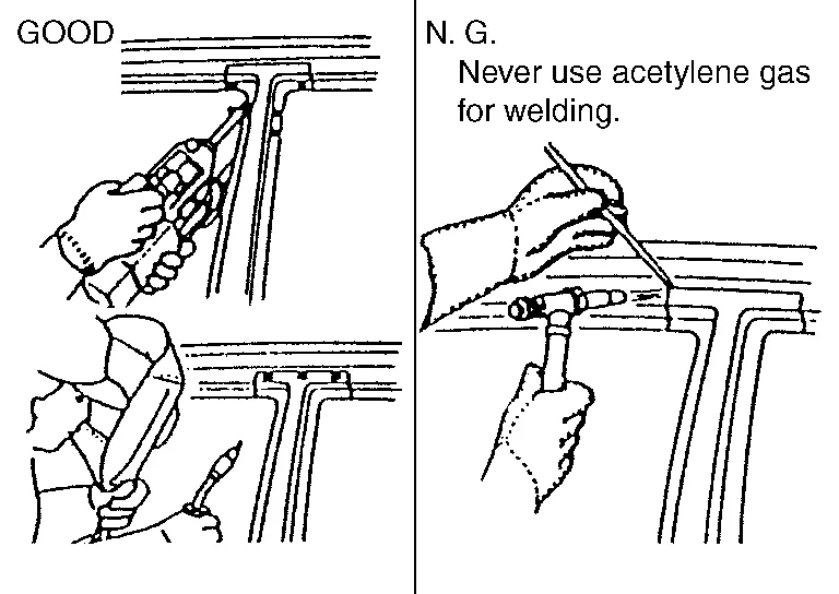
If spot welding is impossible, use MAG welding. Do not use gas (torch) welding because it is inferior in welding strength.
(e) The spot weld on HSS panels is harder than that of an ordinary steel panel.
Therefore, when cutting spot welds on a HSS panel, use a low speed high torque drill (1,000 rpm - 1,200 rpm) to increase drill bit durability and facilitate the operation.
Ultra high strength steel (UHSS) means the steel from 980 MPa or higher.
Never cut and joint the panel, plate and reinforcement made of ultra high strength steel (UHSS).
If such part is damaged, replace the part.
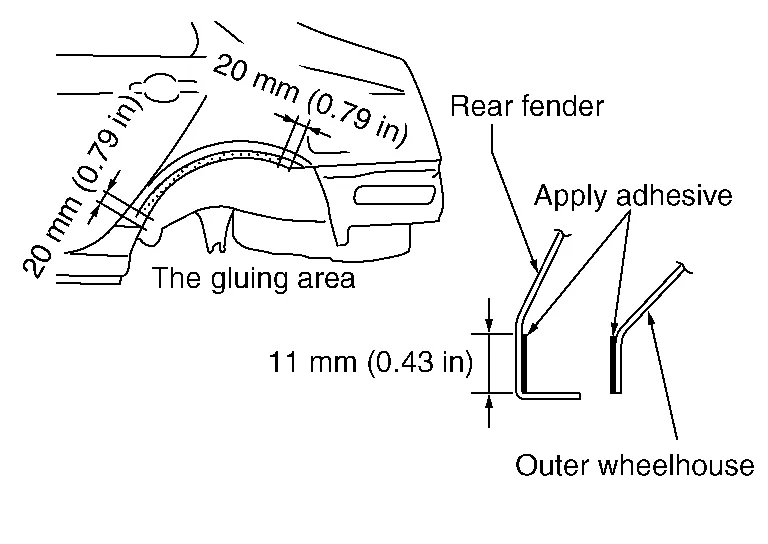
When the rear fender and the outer wheel housing have been joined with adhesive, the panel replacement method described below is used.
-
A wheel arch is to be installed and hemmed over left and right outer wheel house.
-
In order to hem the wheel arch, it is necessary to repair any damaged or defaced parts around outer wheel house.
CAUTION:
Ensure that the area that is to be glued around outer wheelhouse is undamaged or defaced.
Procedure of the hemming process
(a) Remove all coatings, adhesive and corrosion from the bonding area. Use abrasive that will not thin the metal.
(b) Remove all coatings, adhesive and corrosion from the bonding area. Use abrasives that will not thin metal (the replacement part).
(c) Apply new adhesive to both specified areas of outer wheelhouse and rear fender.
| <Adhesive> | 3M™ 08115 Panel Bonding Adhesive or equivalent |
(d) Attach rear fender to the body of the car, and weld the required part except the hemming part.
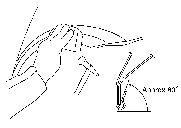
(e) Bend the welded part starting from the center of the wheel arch gradually with a hammer and a dolly. (Also hem the end of the flange.)
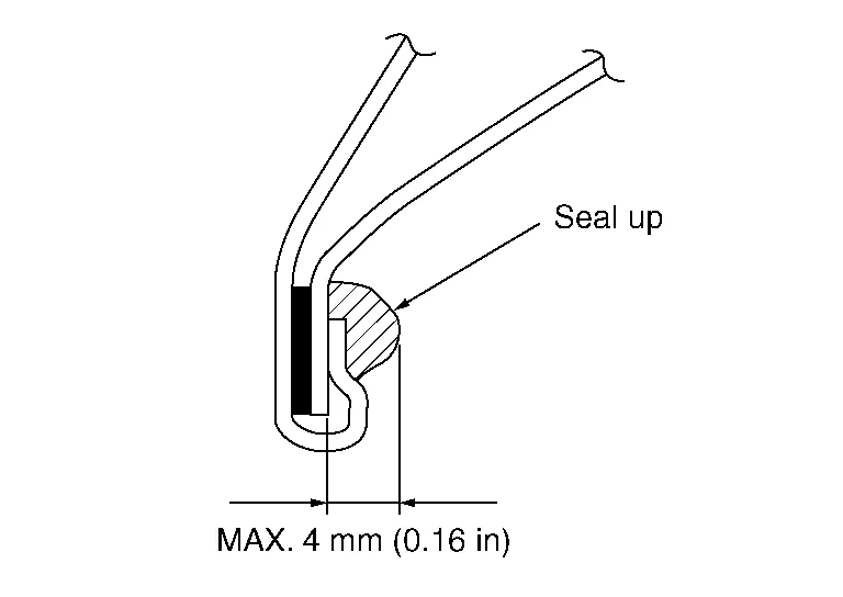
(f) Hemming with a hammer is conducted to an approximate angle of 80°.
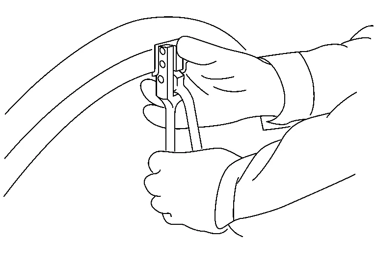
(g) Starting from the center, hem the wheel arch gradually, using slight back and forth motion with a hemming tool [SST: KV991-10000].
(h) Seal up the area around the hemmed end of the flange.
When stud bolts and weld nuts are not welded on the part acquired for repair, and are supplied as separate parts, use the following method to perform welding.
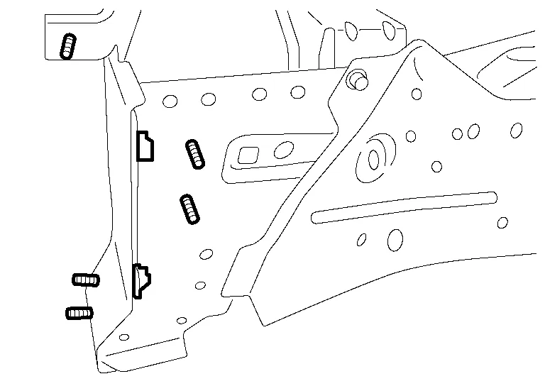
(1) FLANGE BOLT
-
Remove paint, rust, or oils on the surface of the panel.
-
Insert the bolt, temporarily tighten the matching nut of the bolt, and perform centering.
-
Apply zinc weld primer to surfaces to be welded.
-
Weld 3 points evenly by MAG weld. [approximately 3 mm (0.12 in)]
-
Apply an appropriate anti-corrosive treatment to the respective locations.
NOTE:
The same welding method is also applied when welding on a panel surface without a through hole. Welding is performed with the bolt head surface and panel contact surface contacting.
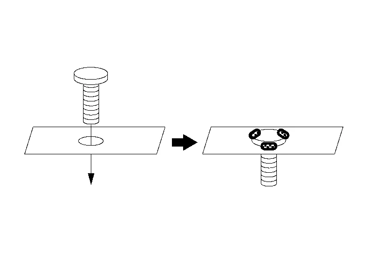
(2) WELD NUT
-
Remove paint, rust, or oils on the surface of the panel.
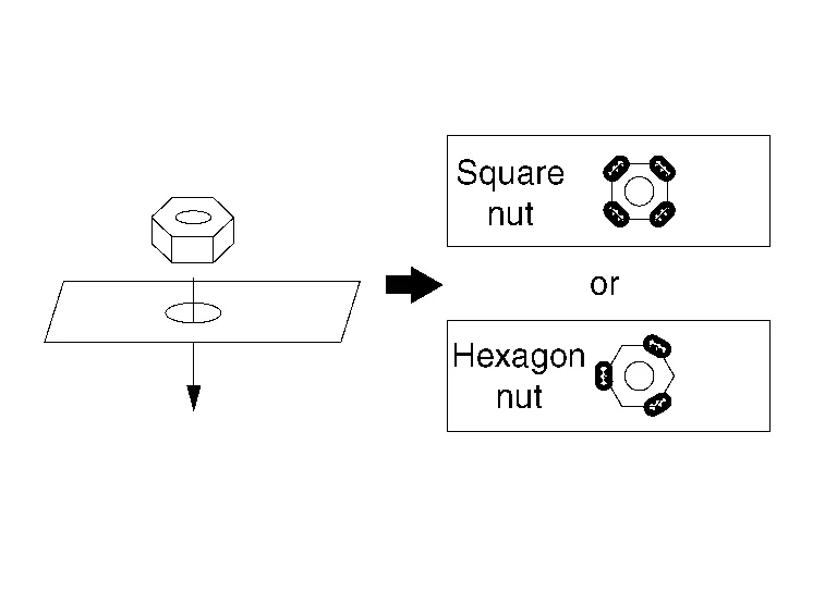
-
Put the nut on the panel center of the hole, temporarily tighten the matching bolt of the nut, and perform centering.
-
Weld 3 or 4 points evenly by MAG weld. [approximately 3 mm (0.12 in)]
-
Apply an appropriate anti-corrosive treatment to the respective locations.
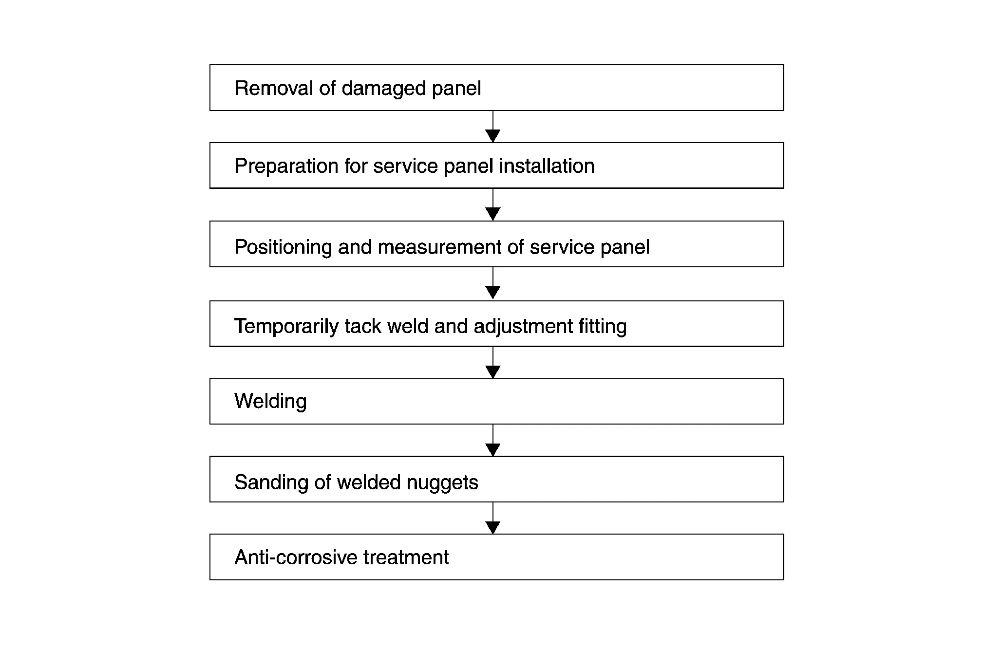
After removing the damaged panel, two operations are needed. Preparation for service panel installation and finishing of the panel mounting portion of the body.
(1) FINISHING BODY
(a) Grind clean around the area where the spot-welded panel has been removed. Thoroughly remove rust and other contamination from the mating surface.
Also, remove paint from the portion to be welded.
Any brazing metal should be thoroughly removed, otherwise welding will be impaired.
(b) Irregularities on the panel mating surface prevent the panel from being welded correctly. Using a hammer and dolly, correct the shape of the mating surface.
(c) Apply weld through primer to flanges or areas where welding will be performed. Apply 3M 5917 Weld- Thru II (or equivalent) and follow product directions for MAG welding in places that cannot be painted in the subsequent painting process.
(d) If it is impossible to apply sealer after welding the service panel, sealer should be applied before welding.
(2) PREPARATION FOR SERVICE PANEL INSTALLATION
(a) The service panel is coated with primer. Remove the primer and apply spot sealer at the portions to be welded. Do not allow the spot sealer to be forced out of the mating surface of the panel.
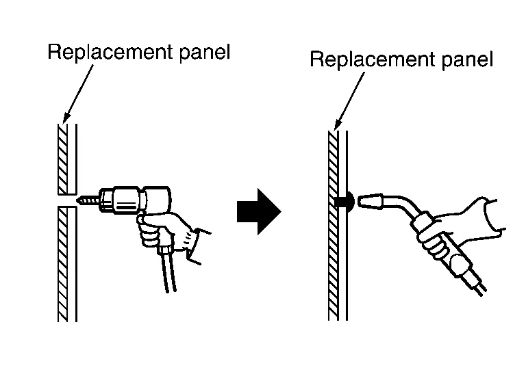
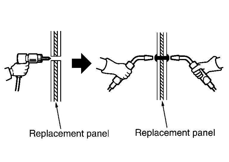
(b) Drill the service panel for plug welding, if necessary.
Refer to the Body Repair Manual of applicable model for the number of holes to be drilled for plug welding. The number of holes must be the same as the number of original spot welds. The drill holes must be spaced equally. Drill hole diameter must be changed according to panel thickness to maintain welding strength.
| Panel thickness | Plug hole dia. |
|---|---|
| Below 1.0 mm (0.039 in) | Below 5 mm (0.20 in) |
|
1.0 mm - 2.4 mm (0.039 in - 0.094 in) |
6.5 mm - 10 mm (0.256 in - 0.394 in) |
| Over 2.4 mm (0.094 in) | Over 10 mm (0.39 in) |
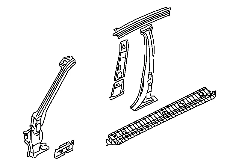
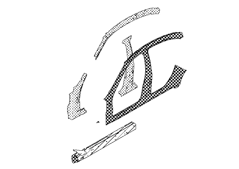
(3) UNDERSTANDING SERVICE PARTS
This is important in judging when the panel should be replaced, or in determining conditions for efficient operation.
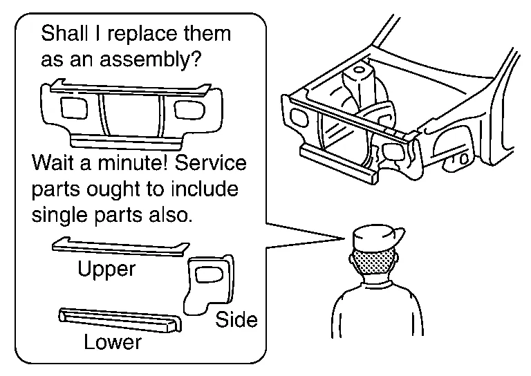
Service parts should be prepared with reference to the Parts Catalog for each model.
The integral type outer body side panel consists of two types of service panels. These service panels need to be cut for use depending on the location and degree of the damage.
| Separate type outer body side panel | Integral type outer body side panel |
|---|---|
|
|
|
Anti-corrosive treatment may be performed on three different occasions (before welding, before painting, and after painting). This section explains anti-corrosive treatment for the latter two occasions.
(1) ANTI-CORROSIVE TREATMENT BEFORE PAINTING
-
Application of body sealer
Body sealer prevents water or mud from entering through the mating surface of the panel. It also prevents formation of corrosion. The sealer nozzle hole should be small. Use a finger or brush to shape the applied sealer. Refer to the Body Repair Manual for body sealer application points.
-
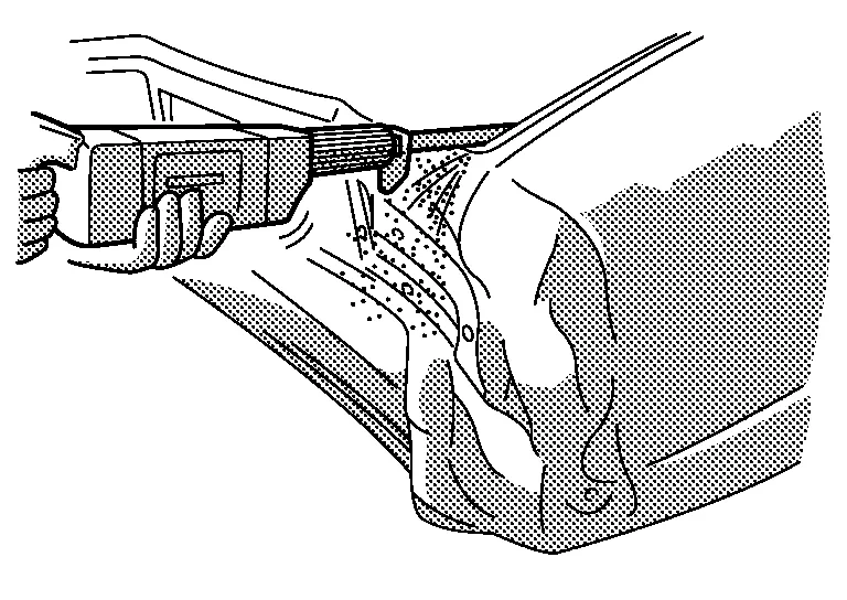
Application of undercoating:
Apply undercoating to the underbody and inside of wheelhouse. Do not apply it to the exhaust pipe, suspension or driving portions. Use approved products 3M Cavity Wax Plus 08852 Anti-Corrosion Spray 18oz aerosol 4 08851 Applicator Wand Kit 8", 24" and 34" tubes.
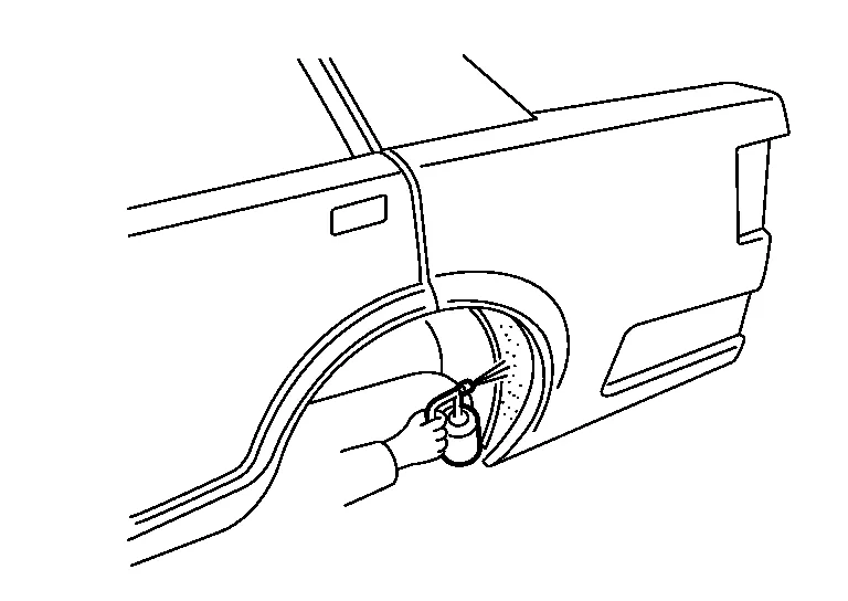
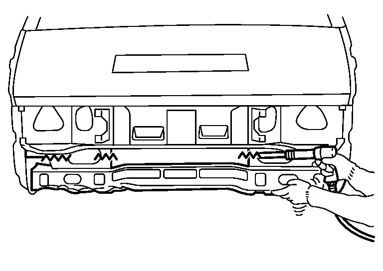
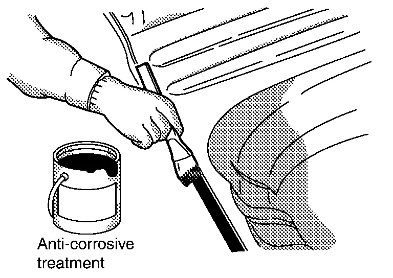
(2) ANTI-CORROSIVE WAX AFTER PAINTING
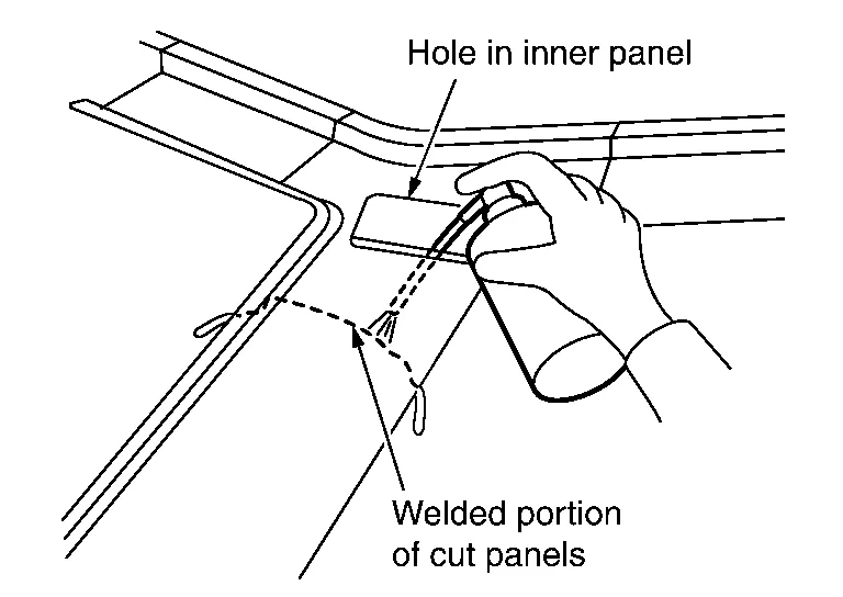
Apply anti-corrosive wax to the back of the panel where painting is difficult. Insert the nozzle of anti-corrosive wax into the holes in the inner panel. Apply until the anti-corrosive wax bleeds out from panel mating surface.
 Replacement of Panel
Replacement of Panel
Panel replacement work includes replacement of the front fenders and hood which are installed by bolts, and replacement of rear fenders and the roof which are welded...
 Use of Body Filler (putty) and Grinding
Use of Body Filler (Putty) and Grinding
Panel irregularities may be corrected with a hammer and dolly. However, exact restoration of the original shape with these tools takes a long time...
Other information:
Nissan Murano (Z52) 2015-2024 Owners Manual: Chassis and body maintenance
Brake lines and cables: Visually inspect for proper installation. Check for chafing, cracks, deterioration, and signs of leaking. Replace any deteriorated or damaged parts immediately. Brake pads and rotors: Check for wear, deterioration and fluid leaks...
Nissan Murano (Z52) 2015-2024 Service Manual: Warning Chime System :: Precaution. Precautions
Precaution for Supplemental Restraint System (SRS) "AIR BAG" and "SEAT BELT PRE-TENSIONER" The Supplemental Restraint System such as “AIR BAG” and “SEAT BELT PRE-TENSIONER”, used along with a front seat belt, helps to reduce the risk or severity of injury to the driver and front passenger for certain types of collisions...
Categories
- Manuals Home
- Nissan Murano Owners Manual
- Nissan Murano Service Manual
- Memory storage function (key-link)
- Intelligent Forward Collision Warning (I-FCW)
- Power Steering Fluid (PSF)
- New on site
- Most important about car
Seatback pockets

Theremaybe one or two seatback pockets located on the back of the driver and passenger seats. The pockets can be used to store maps.
WARNING