
Nissan Murano: Security Control System :: Dtc/circuit Diagnosis / P1611 Id Discord, Immu-Ecm
DTC DETECTION LOGIC
| DTC No. | CONSULT screen terms (Trouble diagnosis content) | DTC Detection Condition | |
|---|---|---|---|
| P1611 |
ID DISCORD, IMMU-ECM (Identification discord immobilizer-engine control unit) |
Diagnosis condition | When ignition switch ON. |
| Signal (terminal) | — | ||
| Threshold | The ID verification results between BCM and ECM are not good | ||
| Diagnosis delay time | — | ||
POSSIBLE CAUSE
-
BCM
-
Harness or connectors
(The CAN communication line is open or shorted.)
-
ECM
FAIL-SAFE
—
PERFORM DTC CONFIRMATION PROCEDURE
 CONSULT
-
Ignition switch ON.
-
Select “Self Diagnostic Result” mode of “ENGINE”.
-
Check DTC.
Is DTC detected?
YES>>Refer to Diagnosis Procedure.
NO>>Inspection End.
PERFORM INITIALIZATION
Perform initialization of BCM and reregistration of all Intelligent Keys. Refer to Work Procedure.
Can the system be initialized and can the engine be started with reregistered Intelligent Key?
YES>>Inspection End.
NO>>GO TO 2.
CHECK SELF DIAGNOSTIC RESULT
CONSULT
-
Select “Self Diagnostic Result” mode of “ENGINE”.
-
Erase DTC.
-
Perform DTC CONFIRMATION PROCEDURE for DTC P1611. Refer to DTC Confirmation Procedure.
Is DTC detected?
YES>>GO TO 3.
NO>>Inspection End.
REPLACE BCM
-
Replace BCM. Refer to Removal and Installation.
-
Perform initialization of BCM and registration of all Intelligent Keys. Refer to Work Procedure.
Can the system be initialized and can the engine be started with registered Intelligent Key?
YES>>Inspection End.
NO>>GO TO 4.
REPLACE ECM
-
Replace ECM. Refer to Removal and Installation.
-
Perform “ADDITIONAL SERVICE WHEN REPLACING ECM”. Refer to Work Procedure.
>>
Inspection End.
 P1610 Lock Mode
DTC Description
DTC DETECTION LOGICNOTE:
If DTC P1610 is displayed with DTC U1000, first perform the trouble diagnosis for DTC U1000. Refer to DTC Description...
 P1612 Chain of Ecm-Immu
DTC Description
DTC DETECTION LOGICNOTE:
If DTC P1612 is displayed with DTC U1000, first perform the trouble diagnosis for DTC U1000. Refer to DTC Description...
Other information:
Nissan Murano (Z52) 2015-2024 Owners Manual: Towing a trailer
WARNING Overloading or improper loading of a trailer and its cargo can adversely affect vehicle handling, braking and performance and may lead to accidents. CAUTION Do not tow a trailer or haul a heavy load for the first 500 miles (805 km). Your engine, axle or other parts could be damaged...
Nissan Murano (Z52) 2015-2024 Service Manual: Engine Control System Symptoms
Symptom Table SYSTEM — BASIC ENGINE CONTROL SYSTEM SYMPTOM Reference page HARD/NO START/RESTART (EXCP. HA) ENGINE STALL HESITATION/SURGING/FLAT SPOT SPARK KNOCK/DETONATION LACK OF POWER/POOR ACCELERATION HIGH IDLE/LOW IDLE ROUGH IDLE/HUNTING IDLING VIBRATION SLOW/NO RETURN TO IDLE OVERHEATS/WATER TEMPERATURE HIGH EXCESSIVE FUEL CONSUMPTION EXCESSIVE OIL CONSUMPTION BATTERY DEAD (UNDER CHARGE) Warranty symptom code AA AB AC AD AE AF AG AH AJ AK AL AM HA Fuel Fuel pump circuit 1 1 2 3 2 2 2 3 2 Diagnosis Procedure Fuel pressure regulator system 3 3 4 4 4 4 4 4 4 4 Work Procedure Fuel injector circuit 1 1 2 3 2 2 2 2 Component Function Check Evaporative emission system 3 3 4 4 4 4 4 4 4 4 System Description Air Positive crankcase ventilation system 3 3 4 4 4 4 4 4 4 4 1 Positive Crankcase Ventilation (PCV) Incorrect idle speed adjustment 1 1 1 1 1 Work Procedure Electric throttle control actuator 1 1 2 3 3 2 2 2 2 2 2 DTC Description, DTC Description Ignition Incorrect ignition timing adjustment 3 3 1 1 1 1 1 1 Work Procedure Ignition circuit 1 1 2 2 2 2 2 2 Component Function Check Power supply and ground circuit 2 2 3 3 3 3 3 2 3 Diagnosis Procedure Mass air flow sensor circuit 1 1 2 2 2 2 2 2 DTC Description, DTC Description Engine coolant temperature sensor circuit 3 3 3 DTC Description, DTC Description Air fuel ratio (A/F) sensor 1 circuit DTC Description, DTC Description, DTC Description, DTC Description, DTC Description Throttle position sensor circuit 2 2 DTC Description, DTC Description, DTC Description, DTC Description, DTC Description Accelerator pedal position sensor circuit 3 2 1 DTC Description, DTC Description, DTC Description, DTC Description Knock sensor circuit 2 3 DTC Description Engine oil temperature sensor 4 2 3 DTC Description, DTC Description Crankshaft position sensor (POS) circuit 2 2 DTC Description Camshaft position sensor (PHASE) circuit 3 2 DTC Description Nissan Murano Vehicle speed signal circuit 2 3 3 3 DTC Description ECM 2 2 3 3 3 3 3 3 3 3 3 DTC Description, DTC Description Intake valve timing control solenoid valve circuit 3 2 1 3 2 2 3 3 DTC Description Intake valve timing intermediate lock control solenoid valve circuit DTC Description Exhaust valve timing control solenoid valve 3 2 1 3 2 2 3 3 DTC Description PNP signal circuit 3 3 3 3 3 DTC Description VIAS control solenoid valve 1 circuit 1 DTC Description VIAS control solenoid valve 2 circuit 1 DTC Description Refrigerant pressure sensor circuit 2 3 3 4 Component Function Check Electrical load signal circuit 3 Component Function Check Air conditioner circuit 2 2 3 3 3 3 3 3 3 3 2 Work Flow ABS actuator and electric unit (control unit) 4 Work Flow 1 - 6: The numbers refer to the order of inspection...
Categories
- Manuals Home
- Nissan Murano Owners Manual
- Nissan Murano Service Manual
- Passenger compartment
- High Beam Assist (if so equipped)
- Vehicle Dynamic Control (VDC) OFF switch
- New on site
- Most important about car
Unfastening the seat belts. Checking seat belt operation
Unfastening the seat belts
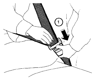
To unfasten the seat belt, press the button
on the buckle  . The seat belt
automatically
retracts.
