Nissan Murano: Dtc/circuit Diagnosis / P1572 Icc Brake Switch
DTC DETECTION LOGIC
 NOTE:
NOTE:
This self-diagnosis has the one trip detection logic. When malfunction A is detected, DTC is not stored in ECM memory. And in that case, 1st trip DTC and 1st trip freeze frame data are displayed. 1st trip DTC is erased when ignition switch OFF. And even when malfunction A is detected in two consecutive trips, DTC is not stored in ECM memory.
-
When the vehicle speed is above 30 km/h (19 MPH), ON signals from the stop lamp switch and the brake pedal position switch (ICC brake switch) are sent to the ECM at the same time.
-
brake pedal position switch (ICC brake switch) signal is not sent to ECM for extremely long time while the Nissan Murano vehicle is driving.
| DTC |
CONSULT screen terms (Trouble diagnosis content) |
DTC detection condition | ||
| P1572 |
ASCD BRAKE SW (ICC brake switch) |
1 | Diagnosis condition | — |
| Signal (terminal) |
|
|||
| Threshold | When the Nissan Murano vehicle speed is above 30 km/h (19 MPH), ON signals from the stop lamp switch and the brake pedal position switch are sent to the ECM at the same time | |||
| Diagnosis delay time | — | |||
| 2 | Diagnosis condition | — | ||
| Signal (terminal) | Brake pedal position switch signal | |||
| Threshold | Brake pedal position switch signal is not sent to ECM for extremely long time while the Nissan Murano vehicle is driving | |||
| Diagnosis delay time | Extremely long time | |||
POSSIBLE CAUSE
DTC P1572 - 1
-
Harness or connectors
(The stop lamp switch circuit is shorted.)
-
Harness or connectors
(The brake pedal position switch circuit is shorted.)
-
Stop lamp switch
-
Brake pedal position switch
-
ICC brake hold relay
-
Incorrect stop lamp switch installation
-
Incorrect brake pedal position switch installation
-
ECM
DTC P1572 - 2
-
Harness or connectors
(The stop lamp switch circuit is shorted.)
-
Harness or connectors
(The brake pedal position switch circuit is shorted.)
-
Stop lamp switch
-
Brake pedal position switch
-
ICC brake hold relay
-
Incorrect stop lamp switch installation
-
Incorrect brake pedal position switch installation
-
ECM
FAIL-SAFE
Not applicable
CHECK DTC PRIORITY
If DTC P1572 is displayed with DTC P0605, first perform the confirmation procedure for DTC P0605.
Is applicable DTC detected?
YES>>Perform diagnosis of applicable. Refer to DTC Description.
NO>>GO TO 2.
PRECONDITIONING
If DTC Confirmation Procedure has been previously conducted, always turn ignition switch OFF and wait at least 10 seconds before conducting the next test.
NOTE:
Procedure for malfunction B is not described here. It takes extremely long time to complete procedure for malfunction B. By performing procedure for malfunction A, the incident that causes malfunction B can be detected.
>>
GO TO 3.
PERFORM DTC CONFIRMATION PROCEDURE 1-I
-
Start engine (VDC switch OFF).
-
Select “DATA MONITOR” mode with CONSULT.
-
Press MAIN switch and make sure that CRUISE lamp lights up.
-
Drive the Nissan Murano vehicle for at least 5 consecutive seconds under the following conditions.
CAUTION:
Always drive Nissan Murano vehicle at a safe speed.
NOTE:
This procedure may be conducted with the drive wheels lifted in the shop or by driving the Nissan Murano vehicle. If a road test is expected to be easier, it is unnecessary to lift the vehicle.
VHCL SPEED SE More than 30 km/h (19 mph) Selector lever Suitable position -
Check 1st trip DTC.
Is 1st trip DTC detected?
YES>>Go to Diagnosis Procedure.
NO>>GO TO 4.
PERFORM DTC CONFIRMATION PROCEDURE 1-II
-
Drive the Nissan Murano vehicle for at least 5 consecutive seconds under the following conditions.
CAUTION:
Always drive Nissan Murano vehicle at a safe speed.
NOTE:
This procedure may be conducted with the drive wheels lifted in the shop or by driving the Nissan Murano vehicle. If a road test is expected to be easier, it is unnecessary to lift the vehicle.
VHCL SPEED SE More than 30 km/h (19 mph) Selector lever Suitable position Driving location Depress the brake pedal for more than five seconds so as not to come off from the above-mentioned Nissan Murano vehicle speed. -
Check 1st trip DTC.
Is 1st trip DTC detected?
YES>>Go to Diagnosis Procedure.
NO>>To check malfunction symptom before repair: Refer to Intermittent Incident.
NO>>Confirmation after repair: INSPECTION END
CHECK DTC PRIORITY
If DTC P1572 is displayed with DTC P0605, first perform the confirmation procedure for DTC P0605.
Is applicable DTC detected?
YES>>Perform diagnosis of applicable. Refer to DTC Description.
NO>>GO TO 2.
CHECK OVERALL FUNCTION-I
 With CONSULT
-
Turn ignition switch ON.
-
Select “BRAKE SW1” in “DATA MONITOR” mode with CONSULT.
-
Check “BRAKE SW1” indication under the following conditions.
Monitor item Condition Indication BRAKE SW1
(ICC brake switch)Brake pedal Slightly depressed OFF Brake pedal Fully released ON
 Without CONSULT
-
Turn ignition switch ON.
-
Check the voltage between ECM harness connector terminals under the following conditions.
ECM Condition Voltage (V) Connector + – Terminal Terminal E32 140 152 Brake pedal Slightly depressed Approx. 0 Brake pedal Fully released Battery voltage
Is the inspection result normal?
YES>>GO TO 3.
NO>>GO TO 4.
CHECK OVERALL FUNCTION-II
With CONSULT
Select “BRAKE SW2” and check indication under the following conditions.
| Monitor item | Condition | Indication | |
|---|---|---|---|
|
BRAKE SW2 (Stop lamp switch) |
Brake pedal | Slightly depressed | ON |
| Fully released | OFF | ||
Without CONSULT
Check the voltage between ECM harness connector terminals as per the following.
| ECM | Condition | Voltage (V) | |||
|---|---|---|---|---|---|
| Connector | + | – | |||
| Terminal | Terminal | ||||
| E32 | 139 | 152 | Brake pedal | Slightly depressed | Battery voltage |
| Fully released | Approx. 0 | ||||
Is the inspection result normal?
YES>>INSPECTION END
NO>>GO TO 7.
CHECK BRAKE PEDAL POSITION SWITCH POWER SUPPLY
-
Turn ignition switch OFF.
-
Disconnect brake pedal position switch harness connector.
-
Turn ignition switch ON.
-
Check the voltage between brake pedal position switch harness connector and ground.
Brake pedal position switch Ground Voltage Connector Terminal E72 1 Ground Battery voltage
Is the inspection result normal?
YES>>GO TO 5.
NO>>Perform the trouble diagnosis for power supply circuit.
CHECK BRAKE PEDAL POSITION SWITCH INPUT SIGNAL CIRCUIT FOR OPEN AND SHORT
-
Turn ignition switch OFF.
-
Disconnect ECM harness connector.
-
Check the continuity between brake pedal position switch harness connector and ECM harness connector.
Brake pedal position switch ECM Continuity Connector Terminal Connector Terminal E72 2 E32 140 Existed -
Also check harness for short to ground and short to power.
Is the inspection result normal?
YES>>GO TO 6.
NO>>Repair or replace error-detected parts.
CHECK BRAKE PEDAL POSITION SWITCH
Check brake pedal position switch. Refer to Component Inspection (ICC Brake Switch).
Is the inspection result normal?
YES>>INSPECTION END
NO>>Replace brake pedal position switch. Refer to Removal and Installation.
CHECK STOP LAMP SWITCH POWER SUPPLY
-
Turn ignition switch OFF.
-
Disconnect stop lamp switch harness connector.
-
Disconnect ICC brake hold relay harness connector.
-
Check the voltage between stop lamp switch harness connector and ground.
Stop lamp switch Ground Voltage Connector Terminal E38 1 Ground Battery voltage -
Check the voltage between ICC brake hold relay harness connector and ground.
ICC brake hold relay Ground Voltage Connector Terminal E75 5 Ground Battery voltage
Is the inspection result normal?
YES>>GO TO 8.
NO>>Perform the trouble diagnosis for power supply circuit.
CHECK STOP LAMP SWITCH INPUT SIGNAL CIRCUIT
-
Disconnect ECM harness connector.
-
Check the continuity between stop lamp switch harness connector and ECM harness connector.
Stop lamp switch ECM Continuity Connector Terminal Connector Terminal E38 2 E32 139 Existed -
Check the continuity between ICC brake hold relay harness connector and ECM harness connector.
ICC brake hold relay ECM Continuity Connector Terminal Connector Terminal E75 3 E32 139 Existed -
Also check harness for short to ground and short to power.
Is the inspection result normal?
YES>>GO TO 9.
NO>>Repair or replace error-detected parts.
CHECK STOP LAMP SWITCH
Check stop lamp switch. Refer to Component Inspection (Stop Lamp Switch).
Is the inspection result normal?
YES>>GO TO 10.
NO>>Replace stop lamp switch. Refer to Removal and Installation.
CHECK ICC BRAKE HOLD RELAY
Check ICC brake hold relay. Refer to Component Inspection (ICC Brake Hold Relay).
Is the inspection result normal?
YES>>INSPECTION END
NO>>Replace ICC brake hold relay.
CHECK BRAKE PEDAL POSITION SWITCH-I
-
Turn ignition switch OFF.
-
Disconnect brake pedal position switch harness connector.
-
Check the continuity between brake pedal position switch terminals under the following conditions.
Terminals Condition Continuity 1 and 2 Brake pedal Fully released Existed Slightly depressed Not existed
Is the inspection result normal?
YES>>INSPECTION END
NO>>GO TO 2.
CHECK BRAKE PEDAL POSITION SWITCH-II
-
Adjust brake pedal position switch installation. Refer to Adjustment.
-
Check the continuity between brake pedal position switch terminals under the following conditions.
Terminals Condition Continuity 1 and 2 Brake pedal Fully released Existed Slightly depressed Not existed
Is the inspection result normal?
YES>>INSPECTION END
NO>>Replace brake pedal position switch. Refer to Removal and Installation.
CHECK STOP LAMP SWITCH-I
-
Turn ignition switch OFF.
-
Disconnect stop lamp switch harness connector.
-
Check harness continuity between stop lamp switch terminals under the following conditions.
Terminals Condition Continuity 1 and 2 Brake pedal Fully released Not existed Slightly depressed Existed
Is the inspection result normal?
YES>>INSPECTION END
NO>>GO TO 2.
CHECK STOP LAMP SWITCH-II
-
Adjust stop lamp switch installation. Refer to Adjustment.
-
Check harness continuity between stop lamp switch terminals under the following conditions.
Terminals Condition Continuity 1 and 2 Brake pedal Fully released Not existed Slightly depressed Existed
Is the inspection result normal?
YES>>INSPECTION END
NO>>Replace stop lamp switch. Refer to Removal and Installation.
CHECK ICC BRAKE HOLD RELAY
-
Turn ignition switch OFF.
-
Remove ICC brake hold relay.
-
Check the continuity between ICC brake hold relay terminals under the following conditions.
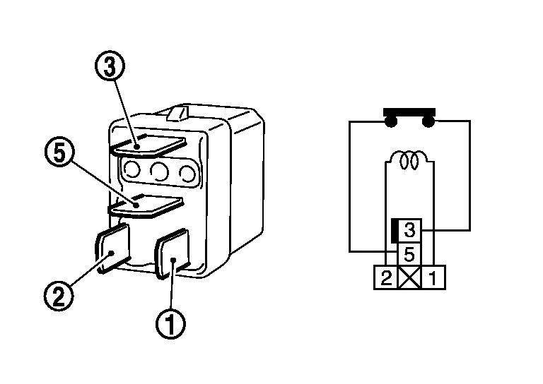
Terminals Condition Continuity 3 and 5 12V direct current supply between terminals 1 and 2 Existed No current supply Not existed
Is the inspection result normal?
YES>>INSPECTION END
NO>>Replace ICC brake hold relay
 P1572 Ascd Brake Switch
DTC Description
DESCRIPTIONWhen the brake pedal is depressed, brake pedal position switch is turned OFF and stop lamp switch is turned ON. ECM detects the state of the brake pedal by this input of two kinds (ON/OFF signal)...
 P1574 Ascd Vehicle Speed Sensor
DTC Description
DESCRIPTIONThe ECM receives two vehicle speed signals via CAN communication line. One is sent from combination meter, and the other is from TCM (Transmission control module)...
Other information:
Nissan Murano (Z52) 2015-2024 Service Manual: Front Axle :: Unit Disassembly and Assembly. Front Drive Shaft
Exploded View (LH) 1. Shaft with damper 2. Circular clip 3. Dust shield 4. Housing 5. Snap ring 6. Spider assembly 7. Stopper ring 8. Boot 9. Boot band 10. Joint sub-assembly Wheel side Fill with Genuine NISSAN Grease...
Nissan Murano (Z52) 2015-2024 Service Manual: Id Registration Cannot Be Completed
Diagnosis Procedure NOTE: The Signal Tech II Tool [– (J-50190)] can be used to perform the following functions: Refer to the Signal Tech II User Guide for additional information. Activate and display TPMS sensor IDs Display tire pressure reported by the TPMS sensor Read TPMS DTCs Register TPMS sensor IDs CHECK TIRE PRESSURE SENSOR ACTIVATION TOOL Check tire pressure sensor activation tool...
Categories
- Manuals Home
- Nissan Murano Owners Manual
- Nissan Murano Service Manual
- All-Wheel Drive (AWD) (if so equipped)
- Tire rotation
- How to enable/disable the LDW system
- New on site
- Most important about car
LATCH (Lower Anchors and Tethers for CHildren) system

LATCH system lower anchor locations - bench seat
Your vehicle is equipped with special anchor points that are used with LATCH system compatible child restraints. This system may also be referred to as the ISOFIX or ISOFIX compatible system. With this system, you do not have to use a vehicle seat belt to secure the child restraint unless the combined weight of the child and child restraint exceeds 65 lbs. (29.5 kg). If the combined weight of the child and child restraint is greater than 65 lbs. (29.5 kg), use the vehicle’s seat belt (not the lower anchors) to install the child restraint. Be sure to follow the child restraint manufacturer’s instructions for installation.