Nissan Murano: Dtc/circuit Diagnosis / P0441 Evap Control System
DTC DETECTION LOGIC
In this evaporative emission (EVAP) control system, purge flow occurs during non-closed throttle conditions. Purge volume is related to air intake volume. Under normal purge conditions (non-closed throttle), the EVAP canister purge volume control solenoid valve is open to admit purge flow. Purge flow exposes the EVAP control system pressure sensor to intake manifold vacuum.
Under normal conditions (non-closed throttle), sensor output voltage indicates if pressure drop and purge flow are adequate. If not, a malfunction is determined.
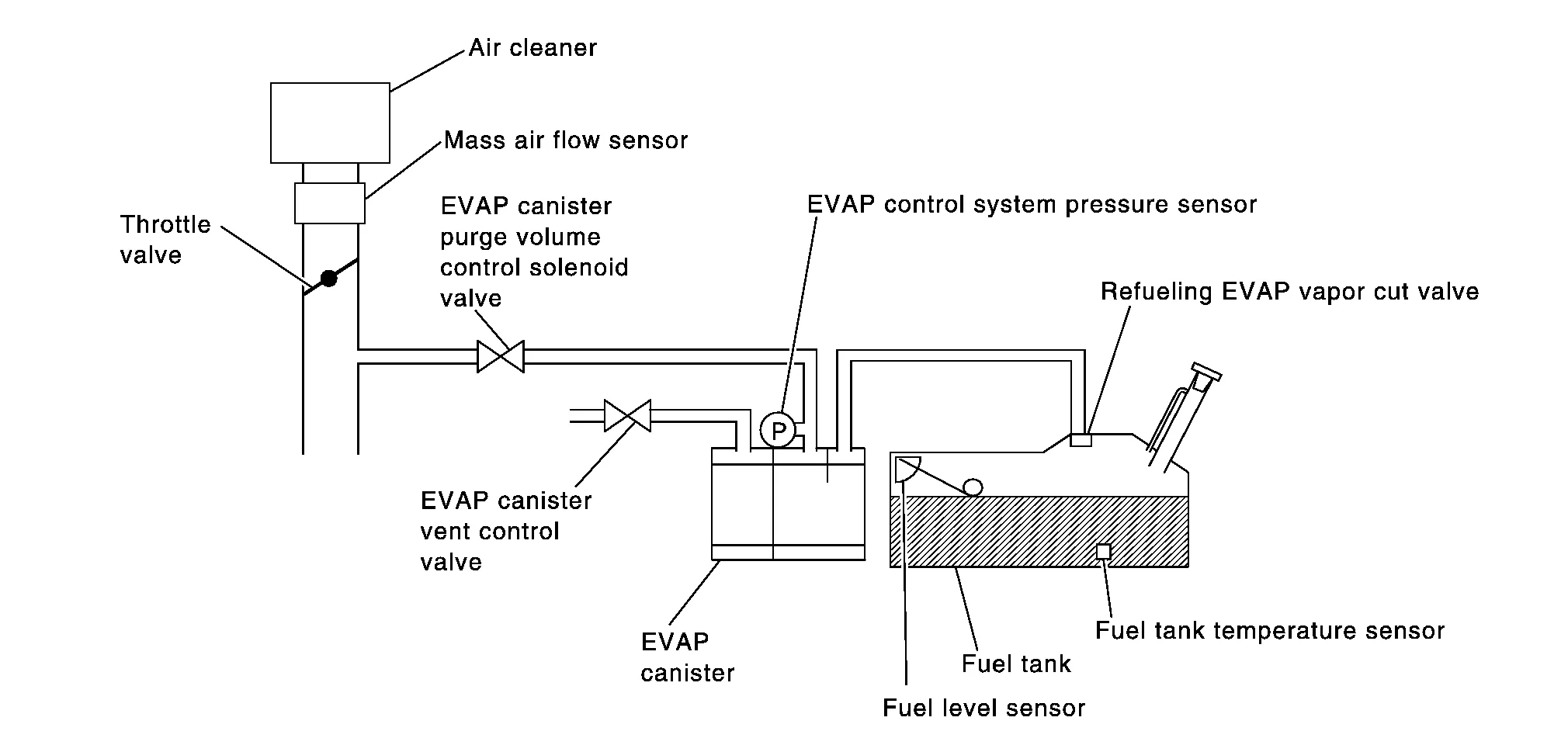
EVAP control system does not operate properly, EVAP control system has a leakage between intake manifold and EVAP control system pressure sensor.
| DTC |
CONSULT screen terms (Trouble diagnosis content) |
DTC detection condition | |
| P0441 |
EVAP PURG FLOW/MON (Evaporative emission system incorrect purge flow) |
Diagnosis condition | — |
| Signal (terminal) | — | ||
| Threshold | EVAP control system does not operate properly, EVAP control system has a leakage between intake manifold and EVAP control system pressure sensor | ||
| Diagnosis delay time | — | ||
POSSIBLE CAUSE
-
EVAP canister purge volume control solenoid valve stuck closed
-
EVAP control system pressure sensor and the circuit
-
Loose, disconnected or improper connection of rubber tube
-
Blocked rubber tube
-
Cracked EVAP canister
-
EVAP canister purge volume control solenoid valve circuit
-
Accelerator pedal position sensor
-
Blocked purge port
-
EVAP canister vent control valve
FAIL-SAFE
Not applicable
CHECK DTC PRIORITY
If DTC P0441 is displayed with other DTC such as P2122, P2123, P2127, P2128 or P2138, first perform trouble diagnosis for other DTC.
Is applicable DTC detected?
YES>>Perform diagnosis of applicable. Refer to DTC Index.
NO>>GO TO 2.
INSPECTION START
Will CONSULT be used?
Will CONSULT be used?
YES>>GO TO 3.
NO>>GO TO 7.
PRECONDITIONING
If DTC Confirmation Procedure has been previously conducted, always perform the following before conducting the next test.
-
Turn ignition switch OFF and wait at least 10 seconds.
-
Turn ignition switch ON.
-
Turn ignition switch OFF and wait at least 10 seconds.
TESTING CONDITION:
Always perform test at a temperature of 5°C (41°F) or more.
>>
GO TO 4.
PERFORM DTC CONFIRMATION PROCEDURE-I
 With CONSULT
-
Start engine and warm it up to normal operating temperature.
-
Turn ignition switch OFF and wait at least 10 seconds.
-
Turn ignition switch ON.
-
Turn ignition switch OFF and wait at least 10 seconds.
-
Start engine and let it idle for at least 70 seconds.
-
Select “PURG FLOW P0441” of “EVAPORATIVE SYSTEM” in “DTC WORK SUPPORT” mode with CONSULT.
-
Touch “START”.
Is “COMPLETED” displayed on CONSULT screen?
YES>>GO TO 6.
NO>>GO TO 5.
PERFORM DTC CONFIRMATION PROCEDURE-II
When the following conditions are met, “TESTING” will be displayed on the CONSULT screen. Maintain the conditions continuously until “TESTING” changes to “COMPLETED”. (It will take at least 35 seconds.)
| Selector lever | Suitable position |
| VHCL SPEED SE | 32 - 120 km/h (20 - 75 mph) |
| ENG SPEED | 500 - 3,000 rpm |
| B/FUEL SCHDL | 1.25 - 9.0 msec |
| COOLANT TEMP/S | More than 0°C (32°F) |
CAUTION:
Always drive Nissan Murano vehicle at a safe speed.
If “TESTING” does not change for a long time, retry from step 2.
Is “COMPLETED” displayed on CONSULT screen?
YES>>GO TO 6.
NO>>Perform DTC CONFIRMATION PROCEDURE again. GO TO 3.
PERFORM DTC CONFIRMATION PROCEDURE-III
Touch “SELF-DIAG RESULTS”.
Which is displayed on CONSULT screen?
OK-1>>To check malfunction symptom before repair: Refer to Intermittent Incident.
OK-2>>Confirmation after repair: INSPECTION END
NG>>Proceed to Diagnosis Procedure.
PERFORM COMPONENT FUNCTION CHECK
 Without CONSULT
-
Lift up drive wheels.
-
Start engine (VDC switch OFF) and warm it up to normal operating temperature.
-
Turn ignition switch OFF, wait at least 10 seconds.
-
Turn ignition switch ON.
-
Turn ignition switch OFF, wait at least 10 seconds.
-
Start engine and wait at least 70 seconds.
-
Set voltmeter probes to ECM harness connector terminals under the following conditions.
ECM Connector + – Terminal E32 121 148 -
Check EVAP control system pressure sensor value at idle speed and note it.
-
Establish and maintain the following conditions for at least 1 minute.
Air conditioner switch ON Head lamp switch ON Rear window defogger switch ON Engine speed Approx. 3,000 rpm Gear position Any position other than P, N or R -
Verify that EVAP control system pressure sensor value stays 0.1 V less than the value at idle speed (measured at step 6) for at least 1 second.
Is the inspection result normal?
YES>>To check malfunction symptom before repair: Refer to Intermittent Incident.
YES>>Confirmation after repair: INSPECTION END
NO>>Proceed to Diagnosis Procedure.
CHECK DTC PRIORITY
If DTC P0441 is displayed with other DTC such as P2122, P2123, P2127, P2128 or P2138, first perform trouble diagnosis for other DTC.
Is applicable DTC detected?
YES>>Perform diagnosis of applicable. Refer to DTC Index.
NO>>GO TO 2.
CHECK EVAP CANISTER
-
Turn ignition switch OFF.
-
Check EVAP canister for cracks.
Is the inspection result normal?
YES>>With CONSULT: GO TO 3.
YES>>Without CONSULT: GO TO 4.
NO>>Replace EVAP canister. Refer to Removal and Installation.
CHECK PURGE FLOW
With CONSULT
-
Disconnect vacuum hose connected to EVAP canister purge volume control solenoid valve at EVAP service port and install vacuum gauge. For the location of EVAP service port, refer to System Description.
-
Start engine and let it idle.
-
Select “PURG VOL C/V” in “ACTIVE TEST” mode with CONSULT.
-
Touch “Qd” and “Qu” on CONSULT screen to adjust “PURG VOL C/V” opening and check vacuum existence.
PURG VOL C/V Vacuum 100% Existed 0% Not existed
Is the inspection result normal?
YES>>GO TO 8.
NO>>GO TO 5.
CHECK PURGE FLOW
Without CONSULT
-
Start engine and warm it up to normal operating temperature.
-
Stop engine.
-
Disconnect vacuum hose connected to EVAP canister purge volume control solenoid valve at EVAP service port and install vacuum gauge. For the location of EVAP service port, refer to System Description.
-
Start engine and let it idle.
Do not depress accelerator pedal even slightly.
-
Check vacuum gauge indication before 60 seconds pass after starting engine.
Vacuum should not exist. -
Rev engine up to 2,000 rpm after 100 seconds pass after starting engine.
Vacuum should exist.
Is the inspection result normal?
YES>>GO TO 8.
NO>>GO TO 5.
CHECK EVAP PURGE LINE
-
Turn ignition switch OFF.
-
Check EVAP purge line for improper connection or disconnection.
Refer to System Description.
Is the inspection result normal?
YES>>GO TO 6.
NO>>Repair EVAP purge line.
CHECK EVAP PURGE HOSE AND PURGE PORT
-
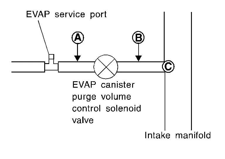
Disconnect purge hoses connected to EVAP service port A and EVAP canister purge volume control solenoid valve B.
-
Blow air into each hose and EVAP purge port C.
-
Check that air flows freely.
Is the inspection result normal?
YES>>With CONSULT: GO TO 7.
YES>>Without CONSULT: GO TO 8.
NO>>Repair or clean hoses and/or purge port.
CHECK EVAP CANISTER PURGE VOLUME CONTROL SOLENOID VALVE
With CONSULT
-
Start engine.
-
Perform “PURG VOL C/V” in “ACTIVE TEST” mode with CONSULT. Check that engine speed varies according to the valve opening.
Does engine speed vary according to the valve opening?
YES>>GO TO 9.
NO>>GO TO 8.
CHECK EVAP CANISTER PURGE VOLUME CONTROL SOLENOID VALVE
Check EVAP canister purge volume control solenoid valve. Refer to Component Inspection.
Is the inspection result normal?
YES>>GO TO 9.
NO>>Replace EVAP canister purge volume control solenoid valve. Refer to Component Parts Location.
CHECK EVAP CONTROL SYSTEM PRESSURE SENSOR CONNECTOR
-
Disconnect EVAP control system pressure sensor harness connector.
-
Check that water is not inside connectors.
Is the inspection result normal?
YES>>GO TO 10.
NO>>Replace EVAP control system pressure sensor. Refer to Removal and Installation.
CHECK EVAP CONTROL SYSTEM PRESSURE SENSOR FUNCTION
Check EVAP control system pressure sensor function. Refer to DTC Description for DTC P0452, DTC Description for DTC P0453.
Is the inspection result normal?
YES>>GO TO 11.
NO>>Replace EVAP control system pressure sensor. Refer to Removal and Installation.
CHECK RUBBER TUBE FOR CLOGGING
-
Disconnect rubber tube connected to EVAP canister vent control valve.
-
Check the rubber tube for clogging.
Is the inspection result normal?
YES>>GO TO 12.
NO>>Clean the rubber tube using an air blower.
CHECK EVAP CANISTER VENT CONTROL VALVE
Check EVAP canister vent control valve. Refer to Component Inspection.
Is the inspection result normal?
YES>>GO TO 13.
NO>>Replace EVAP canister vent control valve. Refer to Removal and Installation.
CHECK EVAP PURGE LINE
Inspect EVAP purge line (pipe and rubber tube). Check for evidence of leakage.
Refer to System Description.
Is the inspection result normal?
YES>>GO TO 14.
NO>>Repair EVAP purge line.
CLEAN EVAP PURGE LINE
Clean EVAP purge line (pipe and rubber tube) using air blower.
>>
INSPECTION END
 P0420 Three Way Catalyst Function
DTC Description
DTC DETECTION LOGICThe ECM monitors the switching frequency ratio of air fuel ratio (A/F) sensor 1 and heated oxygen sensor 2.A three way catalyst (manifold) with high oxygen storage capacity will indicate a low switching frequency of heated oxygen sensor 2...
 P0443 Evap Canister Purge Volume Control Solenoid Valve
DTC Description
DTC DETECTION LOGIC
The canister purge flow is detected during the vehicle is stopped while the engine is running, even when EVAP canister purge volume control solenoid valve is completely closed...
Other information:
Nissan Murano (Z52) 2015-2024 Owners Manual: Getting the spare tire and tools
Open the rear liftgate. Pull up on the handle to lift the carpeted floorboard and attach the hook as shown. Open the storage compartment by pulling on the strap to locate the jack and tools . Remove the jack and tools from the storage area...
Nissan Murano (Z52) 2015-2024 Service Manual: Throttle Control
System Description SYSTEM DIAGRAM*: ECM determines the start signal status by the signals of engine speed and battery voltage.SYSTEM DESCRIPTIONECM calculates the value of signal transmitted from the accelerator pedal and activates the throttle valve by transmitting a control signal to the electric throttle control actuator...
Categories
- Manuals Home
- Nissan Murano Owners Manual
- Nissan Murano Service Manual
- Shift lock release
- Passenger compartment
- All-Wheel Drive (AWD) (if so equipped)
- New on site
- Most important about car
Luggage hooks

When securing items using luggage hooks located on the back of the seat or side finisher do not apply a load over more than 6.5 lbs. (29 N) to a single hook.
The luggage hooks that are located on the floor should have loads less than 110 lbs. (490 N) to a single hook.