Nissan Murano: System / Ldw
SYSTEM DIAGRAM
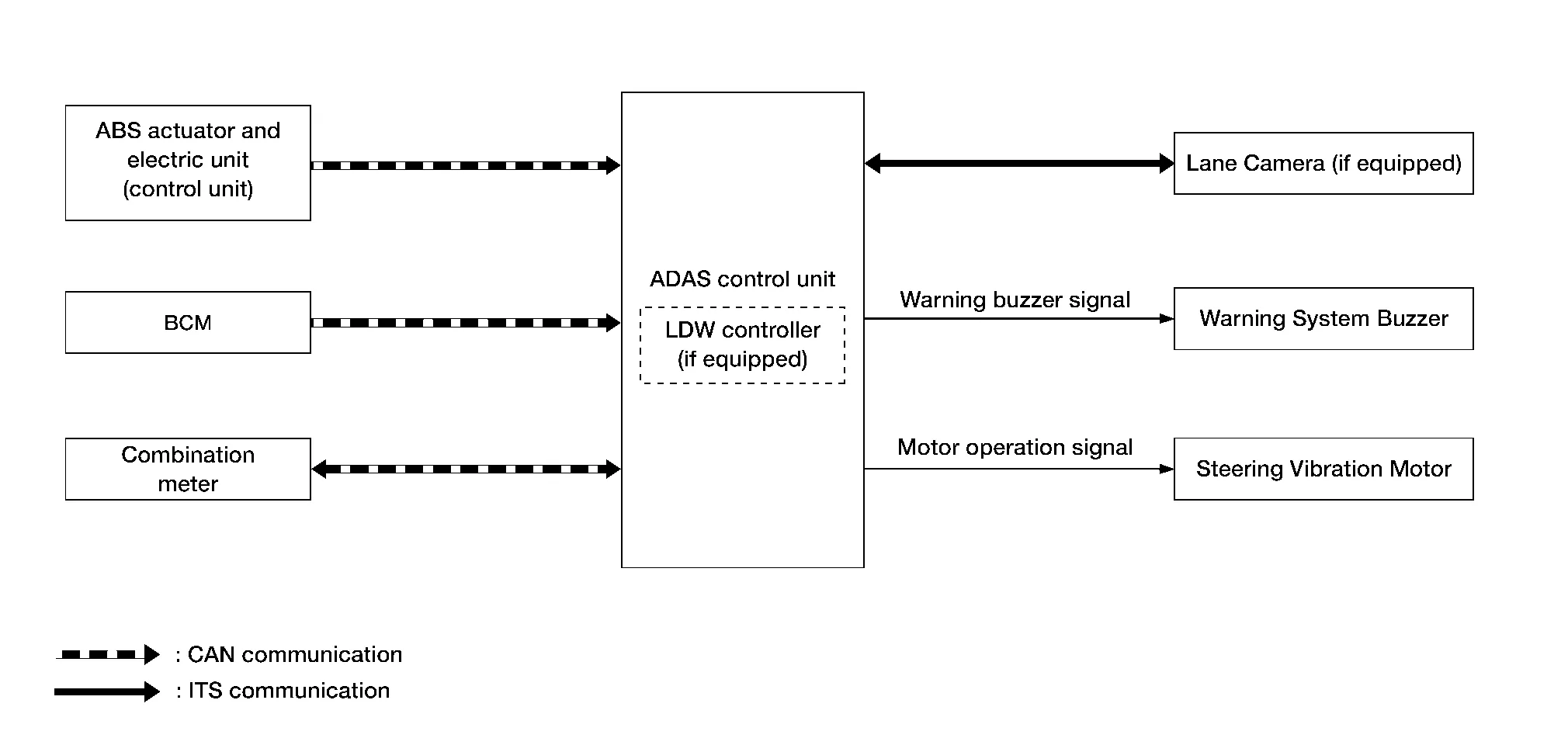
ADAS CONTROL UNIT INPUT/OUTPUT SIGNAL ITEM
Input Signal Item
| Transmit unit | Signal name | Description | ||
|---|---|---|---|---|
| ABS actuator and electric unit (control unit) | CAN communication | Nissan Murano Vehicle speed signal (ABS) | Receives wheel speeds of four wheels | |
| BCM | CAN communication | Turn indicator signal | Receives an operational state of the turn signal lamp and the hazard lamp | |
| Combination meter | CAN communication | System selection signal | Receives a selection state of each item in “Driver Assistance” selected with the Nissan Murano vehicle information display | |
| Lane camera unit | ITS communication | Detected lane condition signal | Receives detection results of lane marker | |
Output Signal Item
| Reception unit | Signal name | Description | ||
|---|---|---|---|---|
| Combination meter | CAN communication | Lane departure warning lamp signal | Transmits a lane departure warning lamp signal to turn ON the lane departure warning lamp | |
| Lane camera unit | ITS communication | Nissan Murano Vehicle speed signal | Transmits a vehicle speed calculated by the ADAS control unit | |
| Turn indicator signal | Transmits a turn indicator signal received from BCM | |||
| Warning system buzzer | Warning buzzer signal | Activates warning system buzzer. | ||
| Steering vibration motor | Motor operation signal | Transmits a motor operation signal to activate the steering vibration motor. | ||
FUNCTION DESCRIPTION
-
Lane Departure Warning (LDW) system provides a lane departure warning function when the vehicle is driven at speeds of approximately 60 km/h (37 MPH) or more.
-
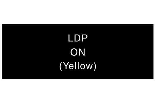
When the Nissan Murano vehicle approaches either the left or the right side of the traveling lane, the steering vibration motor activates and the lane departure warning lamp (yellow) on the combination meter will blink to alert the driver.
-
The warning does not occur during turn signal operation (Lane change side).
-
The warning function will stop when the Nissan Murano vehicle returns inside of the lane markers.
EXAMPLE
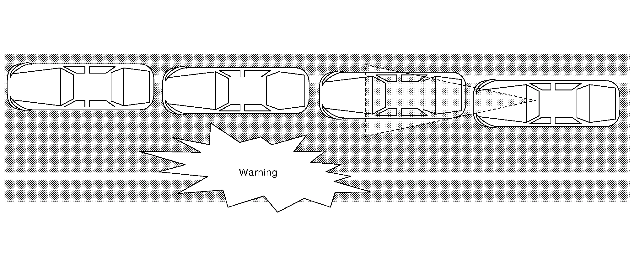
When the vehicle approaches the right lane marker, the driver is alerted by the steering vibration motor, the warning system buzzer and the blinking of lane departure warning lamp (yellow).
OPERATION DESCRIPTION
-
The LDW system setting on the vehicle information display is ON.
-
Lane camera unit monitors lane markers of the traveling lane. It transmits the detected lane condition signal to ADAS control unit via ITS communication.
-
When judging from a lane marker detection signal that the Nissan Murano vehicle is approaching the lane marker, the ADAS control unit controls the following item to alert the driver.
-
Activates the steering vibration motor
-
Activates warning system buzzer
-
ADAS control unit transmits a lane departure warning lamp signal to combination meter via CAN communication and turns ON/OFF the lane departure warning lamp (yellow).
-
OPERATING CONDITION
-
LDW system display (white): ON
-
Vehicle speed: approximately 60 km/h (37 MPH) or more
-
Turn indicator signal: After 2 seconds or more from turned OFF
 NOTE:
NOTE:
-
When the LDW system setting on the Nissan Murano vehicle information display is ON.
-
After the operating conditions of warning are satisfied, the warning continues until the Nissan Murano vehicle speed reaches approximately 50 km/h (30 MPH)
-
I-LI ON indicator lamp is OFF
-
The LDW system may not function properly, depending on the situation. Refer to Precaution For Lane Departure Warning.
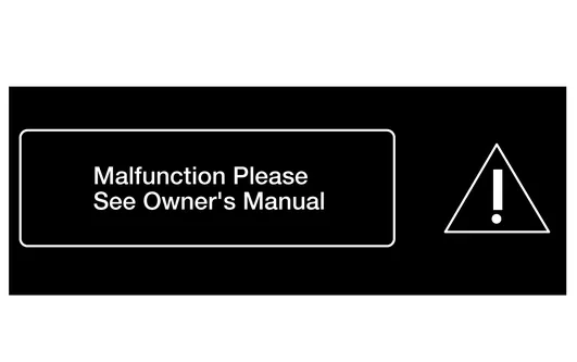
Fail-safe Indication
| Nissan Murano Vehicle condition/ Driver's operation | Warning systems ON indicator | Indication on the combination meter |
|---|---|---|
|
When DTC is detected (Except “C1B01-55” and “C1B03-4B”) |
ON |
|
|
Camera aiming is not completed (“C1B01-55” is detected)
This is detected while driving the Nissan Murano vehicle and the indication remains ON until the ignition switch is pushed OFF |
ON | |
|
When DTC is detected (Except “C1B01-55” and “C1B03-4B”) |
ON |
|
|
Camera aiming is not completed (“C1B01-55” is detected)
This is detected while driving the Nissan Murano vehicle and the indication remains ON until the ignition switch is pushed OFF |
ON | |
|
Temporary disabled status at high temperature (“C1B03-4B” is detected) |
OFF | Unavailable: High Cabin Temp |
 Rcta
Rcta
System Description
SYSTEM DIAGRAMADAS CONTROL UNIT INPUT/OUTPUT SIGNAL ITEMInput Signal Item Transmit unit Signal name Description
TCM
CAN communication
Current gear position signal
Receives a current gear position...
 I-Li
I-Li
System Description
SYSTEM DIAGRAMADAS CONTROL UNIT INPUT/OUTPUT SIGNAL ITEMInput Signal Item Transmit unit Signal name Description
ECM
CAN communication
Brake pedal position switch signal
Receives Brake pedal position switch state
Accelerator pedal position signal
Receives accelerator pedal position (angle)
Stop lamp switch signal
Receives stop lamp switch state
Engine speed signal
Receives engine speed
TCM
CAN communication
Input speed signal
Receives the number of revolutions of input shaft
Current gear position signal
Receives a current gear position
Shift position signal
Receives a selector lever position
Output shaft revolution signal
Receives the number of revolutions of output shaft
ABS actuator and electric unit (control unit)
CAN communication
ABS malfunction signal
Receives a malfunction state of ABS
ABS operation signal
Receives an operational state of ABS
TCS malfunction signal
Receives a malfunction state of TCS
TCS operation signal
Receives an operational state of TCS
VDC OFF switch signal
Receives an ON/OFF state of VDC
VDC malfunction signal
Receives a malfunction state of VDC
VDC operation signal
Receives an operational state of VDC
Nissan Murano Vehicle speed signal (ABS)
Receives wheel speeds of four wheels
Yaw rate signal
Receives yaw rate acting on the Nissan Murano vehicle
Side G sensor signal
Receives lateral G acting on the Nissan Murano vehicle
Combination meter
CAN communication
Parking brake switch signal
Receives an operational state of the parking brake
System selection signal
Receives a selection state of each item in "Driver Assistance"
BCM
CAN communication
Turn indicator signal
Receives an operational state of the turn signal lamp and the hazard lamp
Steering angle sensor
CAN communication
Steering angle sensor malfunction signal
Receives a malfunction state of steering angle sensor
Steering angle sensor signal
Receives the number of revolutions, turning direction of the steering wheel
Steering angle speed signal
Receives the turning angle speed of the steering wheel
Lane intervention switch
Lane intervention switch signal
Receives an ON/OFF state of the lane intervention switch
Lane camera unit
ITS communication
Detected lane condition signal
Receives detection results of lane marker
Output Signal Item Reception unit Signal name Description
ABS actuator and electric unit (control unit)
CAN communication
Target yaw moment signal
Transmits a target yaw moment signal to generate yaw moment to the Nissan Murano vehicle
Combination meter
CAN communication
Intelligent Lane Intervention ON indicator lamp signal
Transmits an Intelligent Lane Intervention ON indicator lamp signal to turn ON the Intelligent Lane Intervention ON indicator lamp
Lane departure warning lamp signal
Transmits an lane departure warning lamp signal to turn ON the lane departure warning lamp
Lane camera unit
ITS communication
Nissan Murano Vehicle speed signal
Transmits a vehicle speed calculated by the ADAS control unit
Turn indicator signal
Transmits a turn indicator signal received from BCM
Steering assist system ON indicator
Steering assist system ON indicator signal
Turns ON the steering assist system ON indicator
Intelligent Lane Intervention system ON indicator
Intelligent Lane Intervention system ON indicator signal
Turns ON the Intelligent Lane Intervention system ON indicator
Warning system buzzer
Warning buzzer signal
Activates warning system buzzer...
Other information:
Nissan Murano (Z52) 2015-2024 Service Manual: B2112 Seat Slide
DTC Description DTC DETECTION LOGIC DTC No. CONSULT screen terms (Trouble diagnosis content) DTC Detection Condition B2112 SEAT SLIDE (Seat slide) Diagnosis condition When ignition switch ON. Signal (terminal) Sliding motor LH circuit (terminals 1 and 5 to ground) Threshold Approx...
Nissan Murano (Z52) 2015-2024 Service Manual: System
System Description SYSTEM DIAGRAMAround View Monitor Control Unit Input Signal (CAN Communication)Transmit unitSignal name ABS actuator and electrical unit (Control unit) Wheel speed signal Audio unit Camera switch signal BCM Door switches state signal Combination meter Setting change request signal Hand brake switch signal IPDM E/R Battery voltage signal Sonar control unit Sonar detection display request signal Steering angle sensor Steering angle signal TCM Transmission range indication signal DESCRIPTION This system is equipped with wide-angle cameras on the front, rear and right and left door mirrors...
Categories
- Manuals Home
- Nissan Murano Owners Manual
- Nissan Murano Service Manual
- System malfunction
- GAS STATION INFORMATION
- Intelligent Forward Collision Warning (I-FCW)
- New on site
- Most important about car
LATCH (Lower Anchors and Tethers for CHildren) system

LATCH system lower anchor locations - bench seat
Your vehicle is equipped with special anchor points that are used with LATCH system compatible child restraints. This system may also be referred to as the ISOFIX or ISOFIX compatible system. With this system, you do not have to use a vehicle seat belt to secure the child restraint unless the combined weight of the child and child restraint exceeds 65 lbs. (29.5 kg). If the combined weight of the child and child restraint is greater than 65 lbs. (29.5 kg), use the vehicle’s seat belt (not the lower anchors) to install the child restraint. Be sure to follow the child restraint manufacturer’s instructions for installation.