Nissan Murano: Electrical & Power Control / Charging System :: Basic Inspection. Diagnosis and Repair Workflow
CHARGING SYSTEM DIAGNOSIS WITH 165-DSS-5000P
To test the charging system, use the following special service tool:
-
165-DSS-5000P battery and electrical diagnostic analyzer
 NOTE:
NOTE:
Refer to the applicable instruction manual for proper charging system diagnosis procedures.
OVERALL SEQUENCE
DETAILED FLOW
NOTE:
To ensure a complete and thorough diagnosis, the battery, stater and generator test segments must be done as a set from start to finish.
PRELIMINARY INSPECTION
Perform the preliminary inspection. Refer to Diagnosis Procedure.
>>
GO TO 2.
DIAGNOSIS WITH 165-DSS-5000P
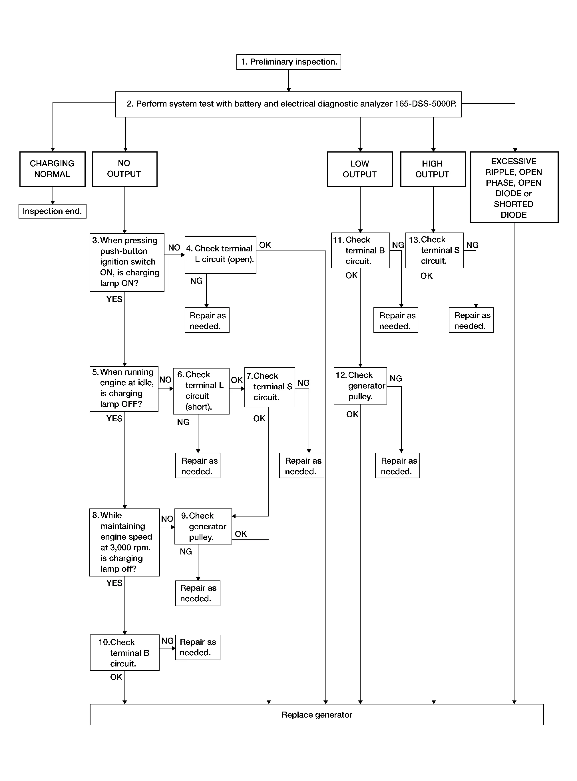
Perform the system test using battery and electrical diagnostic analyzer 165-DSS-5000P. Refer to the applicable instruction manual for proper testing procedures.
Test result
CHARGING NORMAL>>Charging system is normal and will also show “DIODE RIPPLE” test result.
NO OUTPUT>>GO TO 3.
LOW OUTPUT>>GO TO 11.
HIGH OUTPUT>>GO TO 13.
EXCESSIVE RIPPLE, OPEN PHASE, OPEN DIODE or SHORTED DIODE>>Replace the generator. Refer to Removal and Installation. Perform “system test” test again using the 165-DSS-5000P battery and electrical diagnostic analyzer to confirm repair.
INSPECTION WITH CHARGE WARNING LAMP (IGNITION SWITCH ON)
Ignition switch ON.
Does the charge warning lamp illuminate?
YES>>GO TO 5.
NO>>GO TO 4.
“L” TERMINAL CIRCUIT (OPEN) INSPECTION
Check “L” terminal circuit (open). Refer to Diagnosis Procedure.
Is the “L” terminal circuit normal?
YES>>Replace generator. Refer to Removal and Installation.
NO>>Repair as needed.
INSPECTION WITH CHARGE WARNING LAMP (IDLING)
Start the engine and run it at idle.
Does the charge warning lamp turn OFF?
YES>>GO TO 8.
NO>>GO TO 6.
“L” TERMINAL CIRCUIT (SHORT) INSPECTION
Check “L” terminal circuit (short). Refer to Diagnosis Procedure.
Is the “L” terminal circuit normal?
YES>>GO TO 7.
NO>>Repair as needed.
“S” TERMINAL CIRCUIT INSPECTION
Check “S” terminal circuit. Refer to Diagnosis Procedure.
Is the “S” terminal circuit normal?
YES>>GO TO 9.
NO>>Repair as needed.
INSPECTION WITH CHARGE WARNING LAMP (ENGINE AT 3,000 RPM)
Increase and maintain the engine speed at 3,000 rpm.
Does the charge warning lamp remain OFF?
YES>>GO TO 10.
NO>>GO TO 9.
INSPECTION OF GENERATOR PULLEY
Check generator pulley. Refer to Inspection.
Is generator pulley normal?
YES>>Replace generator. Refer to Removal and Installation.
NO>>Repair as needed.
“B” TERMINAL CIRCUIT INSPECTION
Check “B” terminal circuit. Refer to Diagnosis Procedure.
Is “B” terminal circuit normal?
YES>>Replace generator. Refer to Removal and Installation.
NO>>Repair as needed.
“B” TERMINAL CIRCUIT INSPECTION
Check “B” terminal circuit. Refer to Diagnosis Procedure.
Is “B” terminal circuit normal?
YES>>GO TO 12.
NO>>Repair as needed.
INSPECTION OF GENERATOR PULLEY
Check generator pulley. Refer to Inspection.
Is generator pulley normal?
YES>>Replace generator. Refer to Removal and Installation.
NO>>Repair as needed.
“S” TERMINAL CIRCUIT INSPECTION
Check “S” terminal circuit. Refer to Diagnosis Procedure.
Is the “S” terminal circuit normal?
YES>>Replace generator. Refer to Removal and Installation.
NO>>Repair as needed.
OVERALL SEQUENCE
Before performing a generator test, make sure that the battery is fully charged. A 30-volt voltmeter and suitable test probes are necessary for the test.
-
Before starting, inspect the fusible link.
-
Use fully charged battery.
DETAILED FLOW
PRELIMINARY INSPECTION
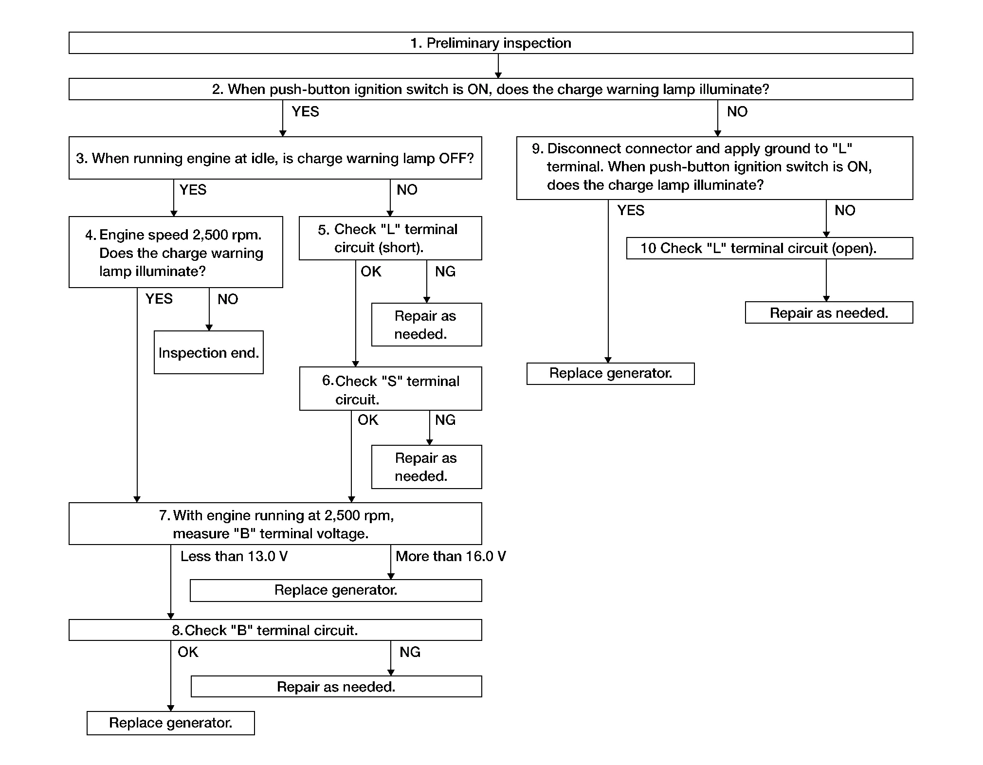
Perform the preliminary inspection. Refer to Diagnosis Procedure.
>>
GO TO 2.
INSPECTION WITH CHARGE WARNING LAMP (IGNITION SWITCH ON)
Ignition switch ON.
Does the charge warning lamp illuminate?
YES>>GO TO 3.
NO>>GO TO 9.
INSPECTION WITH CHARGE WARNING LAMP (IDLING)
Start the engine and run it at idle.
Does the charge warning lamp turn OFF?
YES>>GO TO 4.
NO>>GO TO 5.
INSPECTION WITH CHARGE WARNING LAMP (ENGINE AT 2,500 RPM)
Increase and maintain the engine speed at 2,500 rpm.
Does the charge warning lamp illuminate?
YES>>GO TO 7.
NO>>Inspection End.
“L” TERMINAL CIRCUIT (SHORT) INSPECTION
Check terminal “L” circuit for short. Refer to Diagnosis Procedure.
Is the inspection result normal?
YES>>GO TO 6.
NO>>Repair as needed.
“S” TERMINAL CIRCUIT INSPECTION
Check terminal “S” circuit. Refer to Diagnosis Procedure.
Is the inspection result normal?
YES>>GO TO 7.
NO>>Repair as needed.
MEASURE “B” TERMINAL VOLTAGE
Start engine. With engine running at 2,500 rpm, measure “B” terminal voltage.
What voltage does the measurement result show?
Less than 13.0 V>>GO TO 8.
More than 16.0 V>>Replace generator. Refer to Removal and Installation.
“B” TERMINAL CIRCUIT INSPECTION
Check “B” terminal circuit. Refer to Diagnosis Procedure.
Is the inspection result normal?
YES>>Replace generator. Refer to Removal and Installation.
NO>>Repair as needed.
INSPECTION WITH CHARGE WARNING LAMP (IGNITION SWITCH ON)
-
Disconnect generator connector and apply ground to “L” terminal.
-
Ignition switch ON.
Does the charge warning lamp illuminate?
YES>>Replace generator. Refer to Removal and Installation.
NO>>GO TO 10.
CHECK “L” TERMINAL CIRCUIT (OPEN)
Check “L” terminal circuit open. Refer to Diagnosis Procedure.
>>
Repair as needed.
 System. Charging System
System Description
SYSTEM DIAGRAMSignal transmission function list Component Signal
Combination meter
Charge warning lamp signal
System DescriptionThe generator provides DC voltage to operate the vehicle's electrical system and to keep the battery charged...

Other information:
Nissan Murano (Z52) 2015-2024 Service Manual: Partial Replacement of Panel (welded Panel)
Partial Replacement of Panel (Welded Panel) If damage occurs in a welded panel, it can be entirely replaced by a service panel or partial replacement can be done by cutting and replacing damaged portion with a service panel. Welded Panel Replacement Procedure NOTE: When welding and dressing the parts, cover up holes of these parts with tape to prevent debris from entering...
Nissan Murano (Z52) 2015-2024 Service Manual: Door Check Link
Removal and Installation REMOVALFully close front door window. Remove front door speaker. Refer to Removal and Installation [NAVIGATION WITHOUT BOSE],Removal and Installation [NAVIGATION WITH BOSE]. Remove door check link bolt (body side). Remove door check link bolts (door side)...
Categories
- Manuals Home
- Nissan Murano Owners Manual
- Nissan Murano Service Manual
- Indicator lights
- Passenger compartment
- Shift lock release
- New on site
- Most important about car
Vehicle security system

Your vehicle has two types of security systems:
Vehicle security system NISSAN Vehicle Immobilizer SystemThe vehicle security system provides visual and audible alarm signals if someone opens the doors, liftgate or the hood when the system is armed. It is not, however, a motion detection type system that activates when a vehicle is moved or when a vibration occurs.