
Nissan Murano: Removal and Installation / Lane Intervention Switch

| 1. | Upper switch carrier | 2. | Middle switch carrier | 3. | Heated steering wheel switch (if equipped) |
| 4. | VDC OFF switch | 5. | Automatic back door switch (if equipped) | 6. | Lane intervention switch |
| 7. | Mask | 8. | Lower switch carrier | 9. | Front power return switch (if equipped) |
| 10. | Instrument lower panel LH | 11. | Illumination control switch |
REMOVAL
Remove the instrument lower panel LH. Refer to Removal and Installation.
Remove screws and middle switch carrier from instrument lower panel LH.
Release pawls using a suitable tool.
Remove the lane intervention switch from the middle switch carrier.
INSTALLATION
Installation is in the reverse order of removal.
 Front Camera Unit
Exploded View
1.
Lane camera bracket
2.
Lane camera unit
3.
Inside mirror
4.
Inside mirror finisher
A.
Screw
Metal clip
Pawl
Removal and Installation
REMOVALRelease pawls and metal clips using a suitable tool and remove the inside mirror finisher...
 Steering Vibration Motor
Removal and Installation
The steering vibration motor is an integral part of the steering wheel.
If replacement of the steering vibration motor is necessary, replace the steering wheel...
Other information:
Nissan Murano (Z52) 2015-2024 Service Manual: Hood Lock
Exploded View 1. Hood lock 2. Secondary latch 3. Hood lock release cable 4. Hood lock release handle Clip Removal and Installation REMOVALRemove core support cover. Refer to Exploded View. Disconnect hood lock release cable and secondary latch cable from hood lock...
Nissan Murano (Z52) 2015-2024 Service Manual: Intelligent Key System Symptoms
Diagnosis Procedure NOTE: Perform the self diagnosis result with CONSULT before the symptom diagnosis. Perform the trouble diagnosis if any DTC is detected. SYMPTOM TABLE 1 (BOTH INTELLIGENT KEYS HAVE THE SAME SYMPTOMS) No. Door lock operation (remote keyless entry) Door lock operation (request switch) or back door open operation (opener switch of back door panel) Engine started with ignition switch operation (registered Intelligent Key is within the detection area of inside key antenna) Engine started with ignition switch operation (registered Intelligent Key placed next to ignition switch) Symptom 1 OK OK No start No start Diagnosis Procedure 2 OK NG OK OK Diagnosis Procedure 3 OK NG No crank, No start OK Diagnosis Procedure 4 NG NG No crank, No start OK Diagnosis Procedure 5 NG NG No start No start Diagnosis Procedure 6 OK OK No crank, No start OK Diagnosis Procedure 7 NG OK OK OK Diagnosis Procedure 8 NG NG OK OK Diagnosis Procedure 9 Poor range OK OK OK Diagnosis Procedure SYMPTOM TABLE 2 (ONE INTELLIGENT KEY HAS THE SYMPTOM, OTHER KEYS OPERATE NORMALLY) No...
Categories
- Manuals Home
- Nissan Murano Owners Manual
- Nissan Murano Service Manual
- Fuel recommendation
- Memory storage function (key-link)
- Shift lock release
- New on site
- Most important about car
LATCH (Lower Anchors and Tethers for CHildren) system
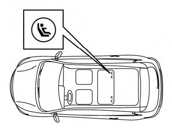
LATCH system lower anchor locations - bench seat
Your vehicle is equipped with special anchor points that are used with LATCH system compatible child restraints. This system may also be referred to as the ISOFIX or ISOFIX compatible system. With this system, you do not have to use a vehicle seat belt to secure the child restraint unless the combined weight of the child and child restraint exceeds 65 lbs. (29.5 kg). If the combined weight of the child and child restraint is greater than 65 lbs. (29.5 kg), use the vehicle’s seat belt (not the lower anchors) to install the child restraint. Be sure to follow the child restraint manufacturer’s instructions for installation.
