Nissan Murano: General Information :: How to Use This Manual / How to Use This Manual
This volume explains “Removal, Disassembly, Installation, Inspection and Adjustment” and “Trouble Diagnoses”.
-
The captions WARNING and CAUTION warn you of steps that must be followed to prevent personal injury and/or damage to some part of the Nissan Murano vehicle.
WARNING indicates the possibility of personal injury if instructions are not followed.
CAUTION indicates the possibility of component damage if instructions are not followed.
BOLD TYPED STATEMENTS except WARNING and CAUTION give you helpful information.
Standard value: Tolerance at inspection and adjustment.
Limit value: The maximum or minimum limit value that should not be exceeded at inspection and adjustment.
-
The UNITS given in this manual are primarily expressed as the SI UNIT (International System of Unit), and alternatively expressed in the metric system and in the yard/pound system.
Also with regard to tightening torque of bolts and nuts, there are descriptions both about range and about the standard tightening torque.
“Example”
Range
Outer Socket Lock Nut : 59 - 78 N·m (6.0 - 8.0 kg-m, 43 - 58 ft-lb) Standard
Drive Shaft Installation Bolt : 44.3 N·m (4.5 kg-m, 33 ft-lb)
-
THE CONTENTS are listed on the first page of each section.
-
THE TITLE is indicated on the upper portion of each page and shows the part or system.
-
THE PAGE NUMBER of each section consists of two or three letters which designate the particular section and a number (e.g. “BR-5”).
-
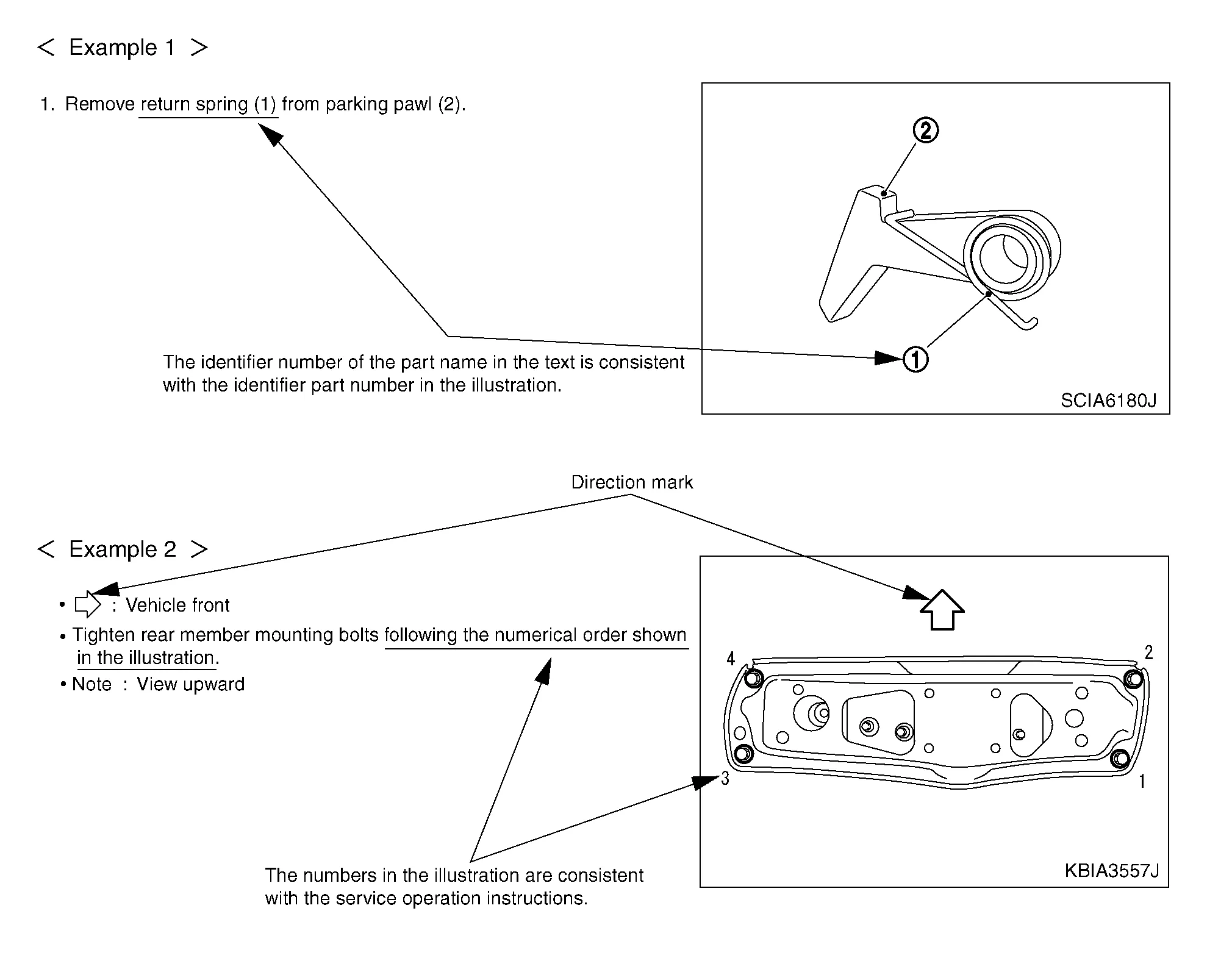
THE SMALL ILLUSTRATIONS show the important steps such as inspection, use of special tools, knacks of work and hidden or tricky steps which are not shown in the previous large illustrations.
Assembly, inspection and adjustment procedures for the complicated units such as the automatic transaxle or transmission, etc. are presented in a step-by-step format where necessary.
The following sample explains the relationship between the part description in an illustration, the part name in the text and the service procedures.
-
THE LARGE ILLUSTRATIONS are exploded views (see the following) and contain tightening torques, lubrication points, section number of the PARTS CATALOG (e.g. SEC. 440) and other information necessary to perform repairs.
The illustrations should be used in reference to service matters only. When ordering parts, refer to the appropriate PARTS CATALOG.
Components shown in an illustration may be identified by a circled number. When this style of illustration is used, the text description of the components will follow the illustration.
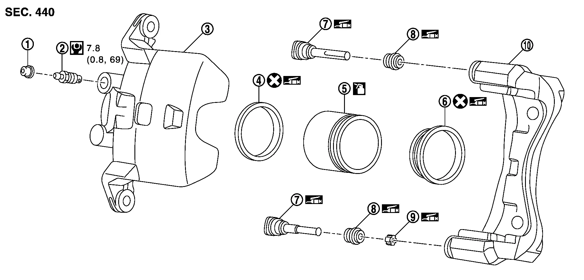
| 1. | Cap | 2. | Bleeder valve | 3. | Cylinder body |
| 4. | Piston seal | 5. | Piston | 6. | Piston boot |
| 7. | Sliding pin | 8. | Sliding pin boot | 9. | Bushing |
| 10. | Torque member | ||||
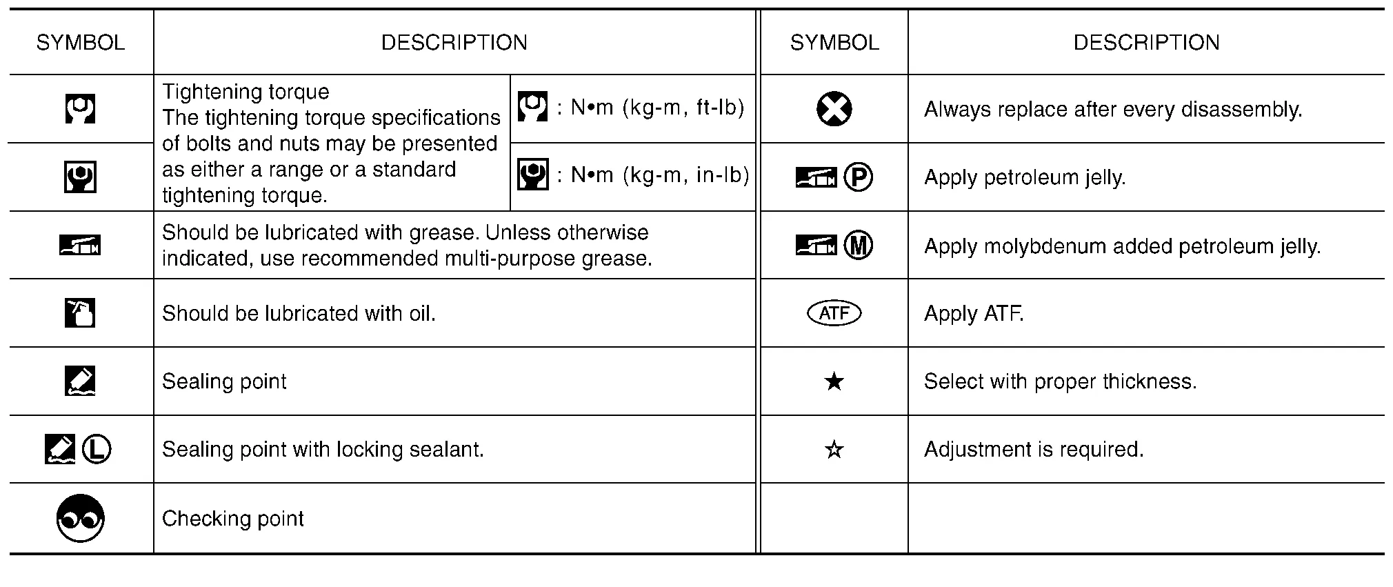
 |
: Apply rubber grease. | ||||
 |
: Apply brake fluid. | ||||
 |
: N·m (kg-m, in-lb) | ||||
 |
: Always replace after every disassembly | ||||
SYMBOLS

 How to Follow Trouble Diagnoses
Description
NOTE:
Trouble diagnoses indicate work procedures required to diagnose problems effectively. Observe the following instructions before diagnosing:
Before performing trouble diagnoses, read the “Work Flow” in each section...
Other information:
Nissan Murano (Z52) 2015-2024 Owners Manual: Class I hitch
Class I trailer hitch equipment (receiver, ball mount and hitch ball) can be used to tow trailers of a maximum weight of 2,000 lbs. (907 kg). Tire pressures When towing a trailer, inflate the vehicle tires to the recommended cold tire pressure indicated on the Tire and Loading Information label...
Nissan Murano (Z52) 2015-2024 Service Manual: Bose Speaker Amp
Exploded View 1. Rear seat support bracket 2. BOSE speaker amp. bracket 3. BOSE speaker amp. Front Removal and Installation REMOVALRemove luggage floor front finisher. Refer to Exploded View. Remove luggage floor side finisher (RH)...
Categories
- Manuals Home
- Nissan Murano Owners Manual
- Nissan Murano Service Manual
- System malfunction
- Checking engine oil level
- Memory storage function (key-link)
- New on site
- Most important about car
Unfastening the seat belts. Checking seat belt operation
Unfastening the seat belts

To unfasten the seat belt, press the button
on the buckle  . The seat belt
automatically
retracts.
. The seat belt
automatically
retracts.