Nissan Murano: General Information :: How to Use This Manual / How to Follow Trouble Diagnoses
 NOTE:
NOTE:
Trouble diagnoses indicate work procedures required to diagnose problems effectively. Observe the following instructions before diagnosing:
-
Before performing trouble diagnoses, read the “Work Flow” in each section.
-
After repairs, re-check that the problem has been completely eliminated.
-
Refer to Component Parts and Harness Connector Location for the Systems described in each section for identification/location of components and harness connectors.
-
When checking circuit continuity, ignition switch should be OFF.
-
Refer to the Circuit Diagram for quick pinpoint check.
If you need to check circuit continuity between harness connectors in more detail, such as when a sub-harness is used, refer to Wiring Diagram in each individual section and Harness Layout in PG section for identification of harness connectors.
-
Before checking voltage at connectors, check battery voltage.
-
After accomplishing the Diagnosis Procedures and Electrical Components Inspection, check that all harness connectors are reconnected as they were.
-
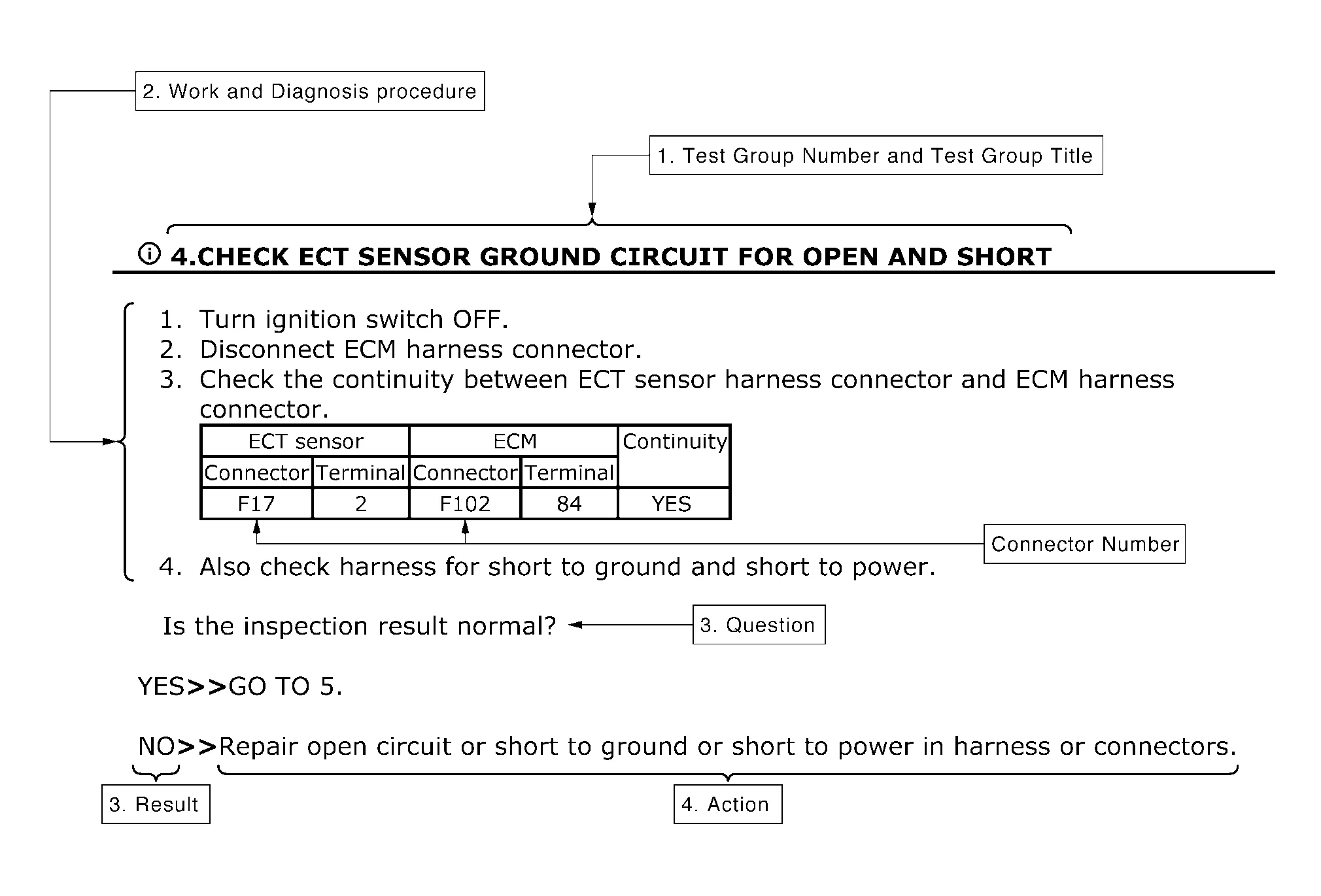
Test group number and test group title
-
Test group number and test group title are shown in the upper portion of each test group.
-
-
Work and diagnosis procedure
-
Start to diagnose a problem using procedures indicated in enclosed test groups.
-
-
Questions and results
-
Questions and required results are indicated in test group.
-
-
Action
-
Next action for each test group is indicated based on result of each question.
-
 How to Use This Manual
Description
This volume explains “Removal, Disassembly, Installation, Inspection and Adjustment” and “Trouble Diagnoses”.
Terms
The captions WARNING and CAUTION warn you of steps that must be followed to prevent personal injury and/or damage to some part of the Nissan Murano vehicle...
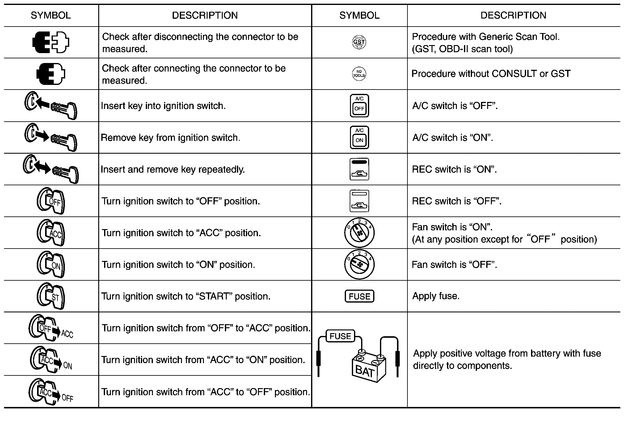
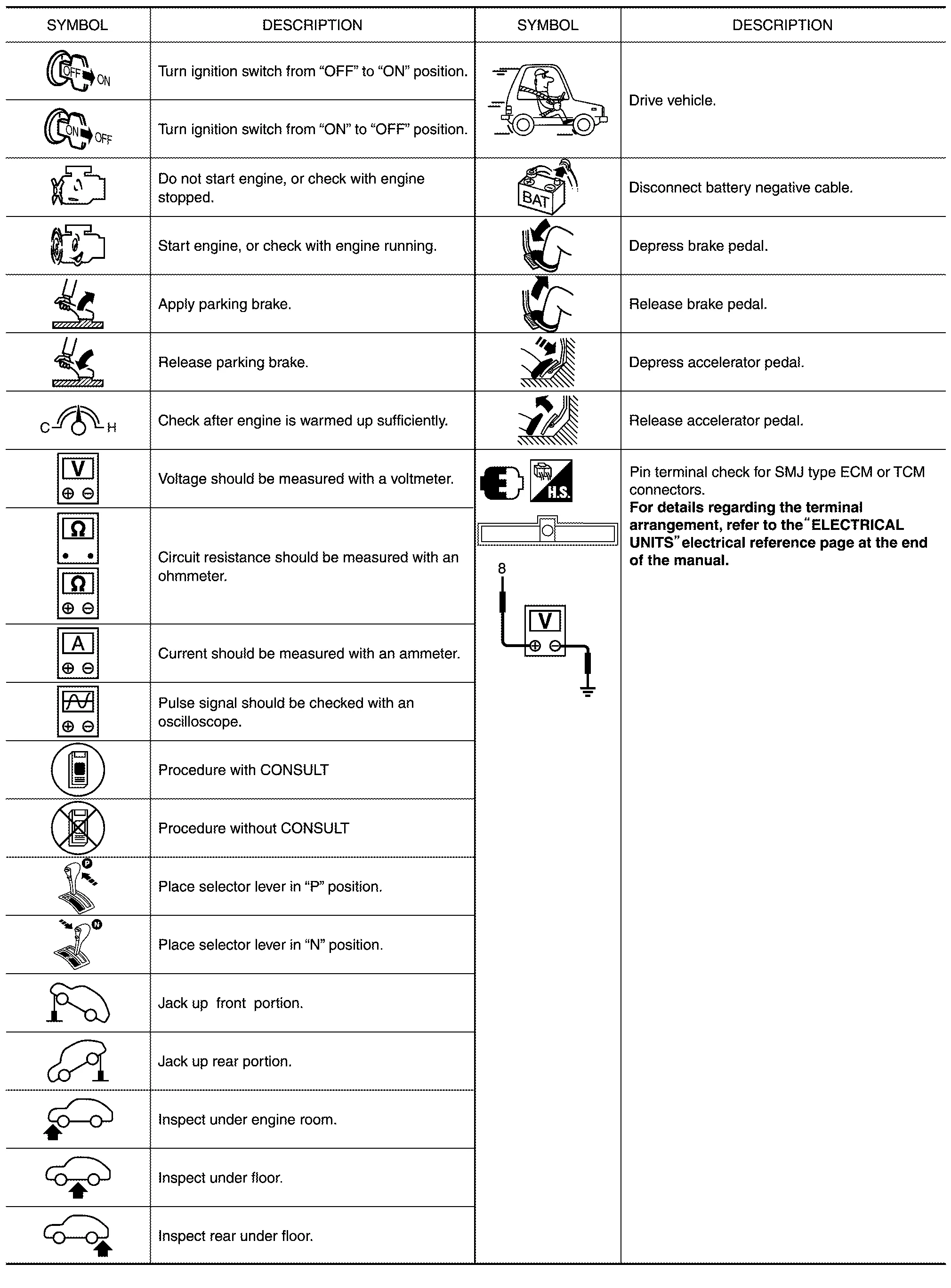
 How to Read Wiring Diagrams
Connector Symbols
Most connector symbols in wiring diagrams are shown from the terminal side.
Connector symbols shown from the terminal side are enclosed by a single line and followed by the direction mark...
Other information:
Nissan Murano (Z52) 2015-2024 Service Manual: C1a34-64 Command Error
DTC Description DTC DETECTION LOGIC DTC No. CONSULT screen items (Trouble diagnosis content) DTC detection condition C1A34–64 COMMAND ERROR (Command error) Diagnosis condition When MAIN switch of ICC system is ON When driving the Nissan Murano vehicle Signal (terminal) CAN communication signal Threshold If an error occurs in the command signal that ADAS control unit transmits to ECM via CAN communication Diagnosis delay time 1 second or less POSSIBLE CAUSEADAS control unitFAIL-SAFEThe following systems are canceled: Vehicle-to-vehicle distance control mode Conventional (fixed speed) cruise control mode Automatic Emergency Braking (AEB) Automatic Emergency Braking (AEB) with pedestrian detection Intelligent Forward Collision Warning (I-FCW) Confirmation Procedure CHECK DTC PRIORITY If DTC “C1A34–64” is displayed with DTC “U1000–01”, first diagnose the DTC “U1000–01”...
Nissan Murano (Z52) 2015-2024 Owners Manual: Maintenance under severe operating conditions
The maintenance intervals shown on the preceding pages are for normal operating conditions. If the vehicle is mainly operated under severe driving conditions as shown below, more frequent maintenance must be performed on the following items as shown in the table...
Categories
- Manuals Home
- Nissan Murano Owners Manual
- Nissan Murano Service Manual
- Settings
- Vehicle Dynamic Control (VDC) OFF switch
- Shift lock release
- New on site
- Most important about car
Luggage hooks

When securing items using luggage hooks located on the back of the seat or side finisher do not apply a load over more than 6.5 lbs. (29 N) to a single hook.
The luggage hooks that are located on the floor should have loads less than 110 lbs. (490 N) to a single hook.