Nissan Murano: Engine Mechanical :: Removal and Installation / Valve Timing Control
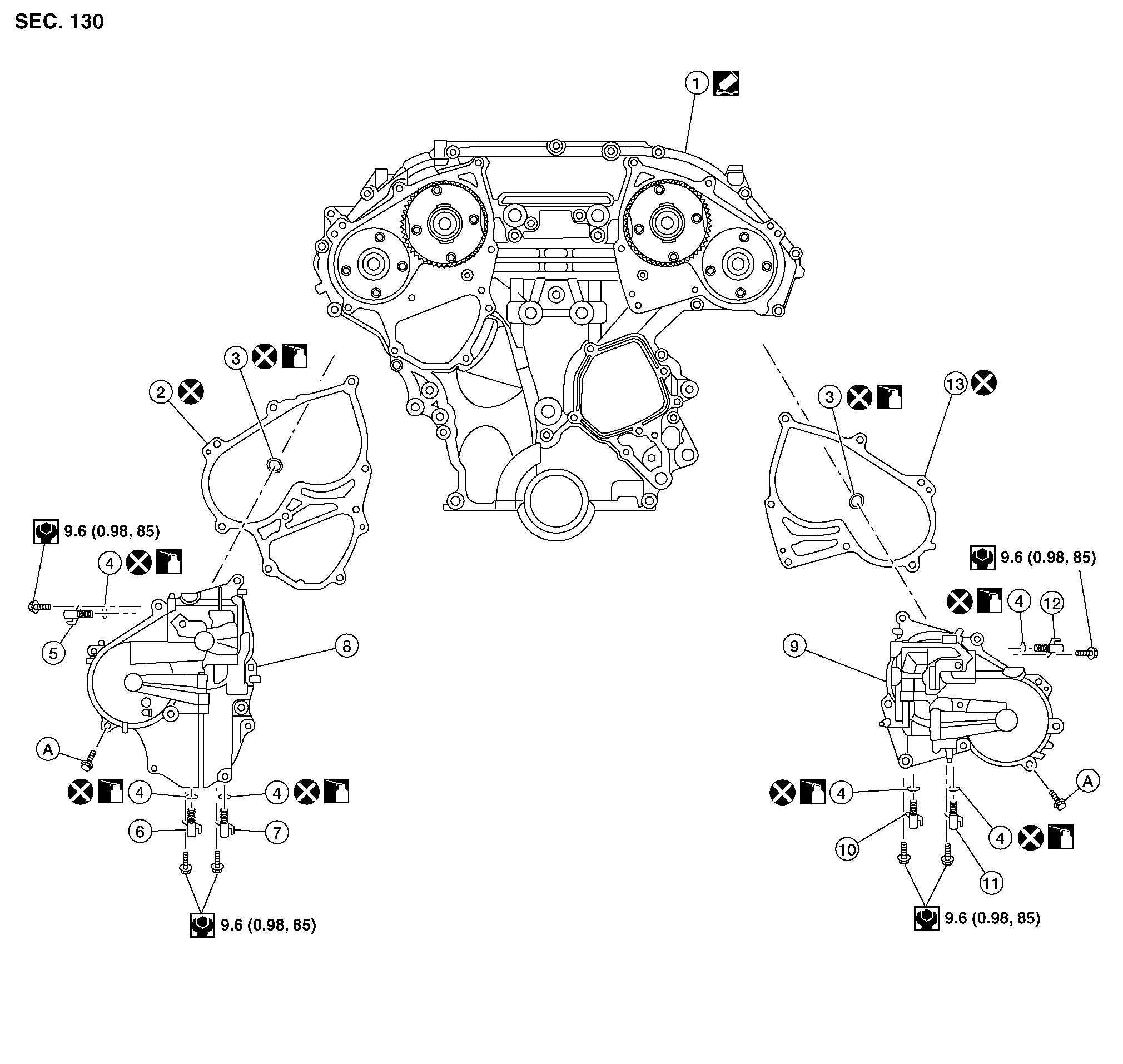
| 1. | Front timing chain case | 2. | Valve timing control cover gasket (bank 1) | 3. | O-ring |
| 4. | O-ring | 5. | Intake valve timing intermediate lock control solenoid valve (bank 1) | 6. | Exhaust valve timing control solenoid valve (bank 1) |
| 7. | Intake valve timing control solenoid valve (bank 1) | 8. | Valve timing control cover (bank 1) | 9. | Valve timing control cover (bank 2) |
| 10. | Intake valve timing control solenoid (bank 2) | 11. | Exhaust valve timing control solenoid (bank 2) | 12. | Intake valve timing intermediate lock control solenoid valve (bank 2) |
| 13. | Valve timing control cover gasket (bank 2) | A. | Refer to Removal and Installation (bank 1) or Removal and Installation (bank 2). |
REMOVAL
Disconnect battery negative terminal. Refer to Removal and Installation.
Remove core support cover. Refer to Exploded View.
Remove front air duct. Refer to Exploded View.
Remove cowl top and cowl top extension. Refer to Exploded View.
Remove reservoir tank. Refer to Exploded View.
Remove power steering oil pump. Refer to Removal and Installation.
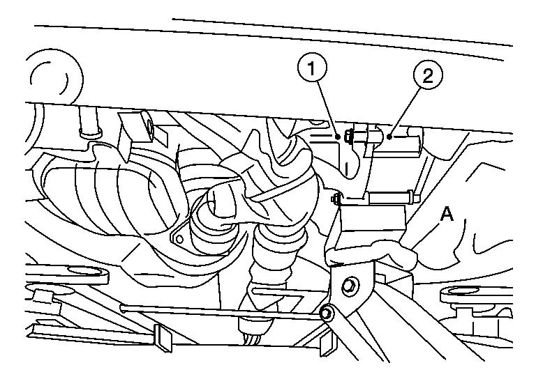
Support engine (1) and transaxle (2) using suitable jack (A).
CAUTION:
-
Position a suitable jack under the engine and transaxle assembly as shown.
-
Do not damage the front exhaust tube or transaxle oil pan with the jack.
Remove upper torque rod, engine mounting insulator (RH), and engine mounting bracket (RH). Refer to Exploded View (FWD) or Exploded View (AWD).
Disconnect the harness connector from intake valve timing intermediate lock control solenoid valve (bank 1).
Disconnect the harness connector from exhaust valve timing control solenoid valve (bank 1).
Disconnect the harness connector from intake valve timing control solenoid valve (bank 1).
Remove intake valve timing intermediate lock control solenoid valve (bank 1), exhaust valve timing control solenoid valve (bank 1), and intake valve timing control solenoid valve (bank 1) from valve timing control cover (bank 1).
CAUTION:
Do not reuse O-rings.
Remove the valve timing control cover (bank 1) and gasket.
INSTALLATION
Install valve timing control cover (bank 1). Refer to Exploded View.
Installation of remaining components is in the reverse order of removal.
CAUTION:
-
Do not reuse valve timing control cover gasket.
-
Do not reuse O-rings.
-
Lubricate O-rings with clean engine oil prior to installation.
REMOVAL
Remove core support cover. Refer to Exploded View.
Remove front air duct. Refer to Removal and Installation.
Remove reservoir tank. Refer to Exploded View.
Remove power steering oil pump. Refer to Removal and Installation.
Disconnect the harness connector from intake valve timing intermediate lock control solenoid valve (bank 2).
Disconnect the harness connector from exhaust valve timing control solenoid valve (bank 2).
Disconnect the harness connector from intake valve timing control solenoid valve (bank 2).
Remove intake valve timing intermediate lock control solenoid valve (bank 2), exhaust valve timing control solenoid valve (bank 2), and intake valve timing control solenoid valve (bank 2) from valve timing control cover (bank 2).
CAUTION:
Do not reuse O-rings.
Remove valve timing control cover (bank 2) and gasket.
INSTALLATION
Install valve timing control cover (bank 2). Refer to Exploded View.
Installation of remaining components is in the reverse order of removal.
CAUTION:
-
Do not reuse valve timing control cover gasket.
-
Do not reuse O-rings.
-
Lubricate O-rings with clean engine oil prior to installation.
 Fuel Injector and Fuel Tube
Exploded View
1.
Fuel feed hose
2.
Quick connector cap
3.
Fuel tube
4.
O-ring
5.
Fuel damper
6.
Fuel damper cap
7.
Clip
8...
 Front Timing Chain Case
Exploded View
1.
Engine assembly
2.
Front timing chain case oil filter
3.
Water pump cover
4.
Crankshaft pulley
5.
Front oil seal
6...
Other information:
Nissan Murano (Z52) 2015-2024 Service Manual: Automatic Emergency Braking System Symptoms
Symptom Table Before performing diagnosis, check that it is not a symptom caused by normal operation. Refer to System Description. Symptom Confirmation item Inspection item/Reference page AEB system display does not illuminate All of system display does not illuminate System settings cannot be turned ON/OFF Refer to Diagnosis Procedure Other information display is not illuminated Combination meter Refer to DTC Index AEB warning lamp does not illuminate All of system display does not illuminate System settings cannot be turned ON/OFF Refer to Diagnosis Procedure Other information display is not illuminated Combination meter Refer to DTC Index AEB warning buzzer is not sounding (Warning display is functioning normally) — Chime does not sound...
Nissan Murano (Z52) 2015-2024 Service Manual: Malfunction Area Chart
Vehicle CAN Communication Circuit MAIN LINE Malfunction area Reference Main line between IPDM E/R and ABS actuator and electric unit (control unit) Diagnosis Procedure Main line between ABS actuator and electric unit (control unit) and A/C auto amp...
Categories
- Manuals Home
- Nissan Murano Owners Manual
- Nissan Murano Service Manual
- All-Wheel Drive (AWD) (if so equipped)
- System malfunction
- Jacking up vehicle and removing the damaged tire
- New on site
- Most important about car
Luggage hooks

When securing items using luggage hooks located on the back of the seat or side finisher do not apply a load over more than 6.5 lbs. (29 N) to a single hook.
The luggage hooks that are located on the floor should have loads less than 110 lbs. (490 N) to a single hook.