Nissan Murano: Engine Mechanical :: Removal and Installation / Front Timing Chain Case
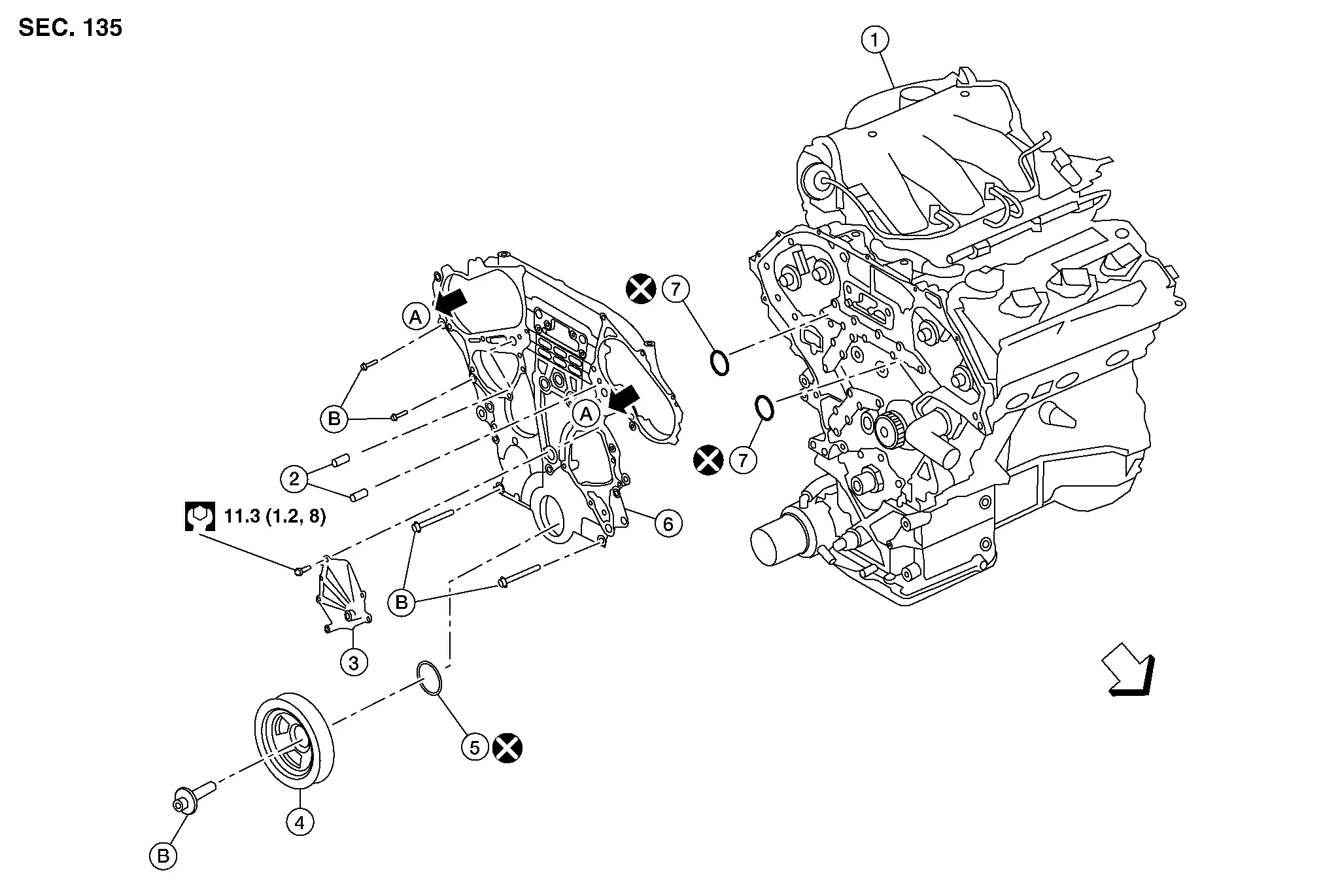
| 1. | Engine assembly | 2. | Front timing chain case oil filter | 3. | Water pump cover |
| 4. | Crankshaft pulley | 5. | Front oil seal | 6. | Front timing chain case |
| 7. | O-ring | A. | To valve timing control cover (bank 1/bank 2). Refer to Valve Timing Control Cover (bank 1) and Valve Timing Control Cover (bank 2). | B. | Refer to Removal and Installation. |
| Front |
 NOTE:
NOTE:
-
This section describes the procedure for removal/installation of the front timing chain case without removing the engine from the Nissan Murano vehicle.
-
When rear timing chain case must be removed, remove the engine from the vehicle. Refer to Removal and Installation (FWD) or Removal and Installation (AWD). Then remove front timing chain case, timing chain related parts, and rear timing chain case in this order, and install in reverse order of removal.
-
When removing components such as hoses, tubes/lines, etc., cap or plug openings to prevent fluid from spilling.
REMOVAL
Remove front under cover. Refer to Removal and Installation.
Drain the engine coolant from the radiator. Refer to Changing Engine Coolant.
Drain the engine oil. Refer to Changing Engine Oil.
Drain the power steering fluid. Refer to Draining and Refilling.
Remove engine room cover. Refer to Removal and Installation.
Remove front air duct. Refer to Exploded View.
Remove battery tray. Refer to Removal and Installation.
Remove cowl top. Refer to Exploded View.
Remove upper radiator hose.
Disconnect engine coolant reservoir hose from the radiator and remove engine coolant reservoir.
Remove cooling fan assembly. Refer to Removal and Installation.
Disconnect lower radiator hose from engine.
Remove the radiator. Refer to Removal and Installation.
Disconnect the power steering fluid reservoir tank hose from the power steering pump and fluid cooler and remove the power steering fluid reservoir tank.
Remove the front wheel and tire (RH) using a power tool. Refer to Removal and Installation.
Remove the fender protector side cover (RH). Refer to Exploded View.
Remove the drive belt. Refer to Removal and Installation.
Remove the rocker covers, if necessary. Refer to Removal and Installation (bank 2) (bank 2) and Removal and Installation (bank 1) (bank 1).
NOTE:
Necessary only when removing timing chains.
If removing the timing chains, obtain compression TDC of No. 1 cylinder as follows:
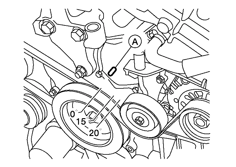
| Engine front |
-
If not, turn the crankshaft one revolution (360°) and align as shown.
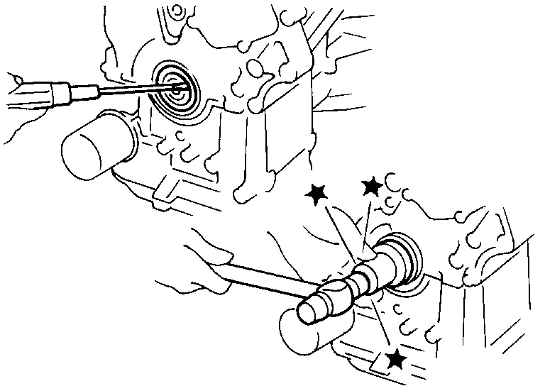
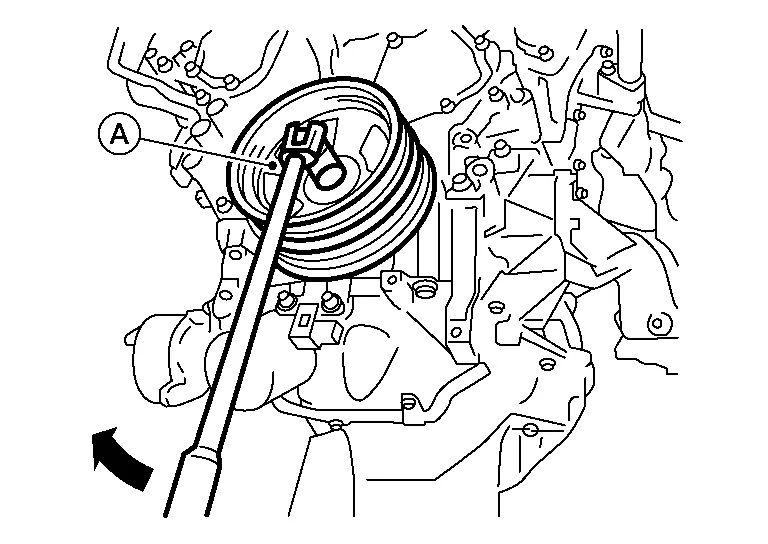
Remove the access plate and lock the ring gear using Tool.
| Tool number | : — (J-50288) |
CAUTION:
Do not damage the ring gear teeth, or the signal plate teeth behind the ring gear, when installing Tool.
Remove the crankshaft pulley as follows:Loosen crankshaft pulley and locate bolt seating surface at 10 mm (0.39 in) from its original position. Position a pulley puller at recess hole of crankshaft pulley to remove crankshaft pulley.

CAUTION:
Do not use a puller claw on crankshaft pulley periphery.
Remove the power steering pump. Refer to Removal and Installation.
Remove the lower oil pan. Refer to Removal and Installation (Lower Oil Pan).
Remove upper oil pan bolts (1) and (2) as shown. Refer to Exploded View (Oil Pan and Oil Strainer).
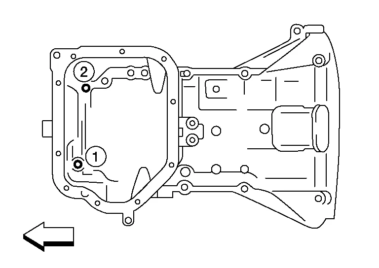
| Engine front |
Remove the generator. Refer to Removal and Installation.
Disconnect the A/C tubes from the A/C compressor and position aside. Refer to Recycle Refrigerant.
Remove the A/C compressor bolts and the A/C compressor. Refer to Removal and Installation.
Support the engine with suitable jack and remove the RH engine insulator, mount and torque rod. Refer to Removal and Installation (FWD) and Removal and Installation (AWD).
Disconnect the oil pressure switch harness connector.
Disconnect the intake valve timing control solenoid valve harness connector.
Remove the valve timing control cover (bank 1) (A) and valve timing control cover (bank 2) (B).
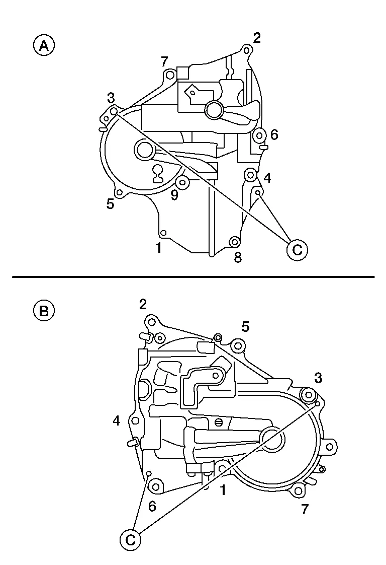
| (C) | : Dowel pin hole |
-
Loosen the intake valve timing control solenoid valve cover bolts in the reverse order as shown.
CAUTION:
The shaft in the intake valve timing control solenoid valve cover is inserted into the center hole of the intake camshaft sprocket. Remove the intake valve timing control solenoid valve cover by pulling straight out until the intake valve timing control solenoid valve cover disengages from the camshaft sprocket.
Remove the drive belt auto-tensioner. Refer to Removal and Installation of Drive Belt Auto-tensioner.
Remove the water pump cover (If necessary).
Remove the front timing chain case.
-
Cut liquid gasket for removal using Tool.
| Tool number: | KV10111100 (J-37228) |
CAUTION:
-
Do not use a screwdriver or similar tool.
-
After removal, handle carefully so it does not bend, or warp under a load.
Remove front upper oil pan gasket. Refer to Exploded View (Oil Pan and Oil Strainer).
Remove O-rings (1) from rear timing chain case.
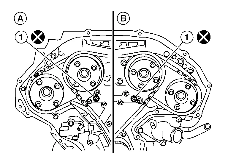
| (A) | : Bank 1 (RH) |
| (B) | : Bank 2 (LH) |
CAUTION:
Do not reuse O-rings.
Remove the front oil seal from the front timing chain case using suitable tool.
CAUTION:
Do not damage the front cover.
Remove all old Silicone RTV Sealant (A) from all the bolt holes (B) and bolts.
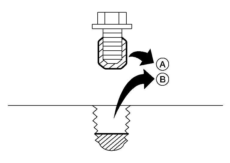
CAUTION:
Do not damage the threads or mating surfaces.
Use a suitable tool (A) to remove all of the old Silicone RTV Sealant from the front timing chain case (B) and opposite mating surfaces.
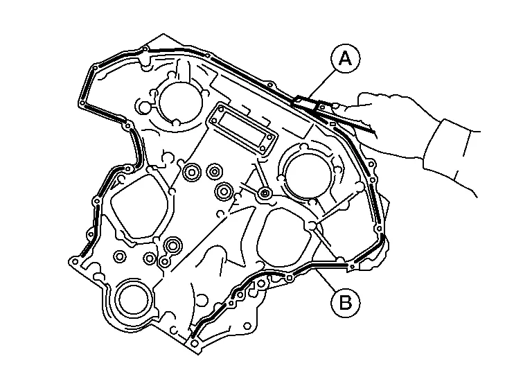
CAUTION:
Do not damage the mating surfaces.
Remove front timing chain case oil filters (if necessary).
INSTALLATION
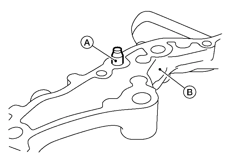
Install front timing chain case oil filter (2) (if necessary).
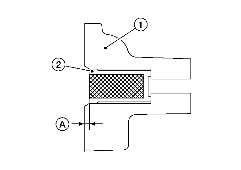
CAUTION:
-
Insert front timing chain case oil filter (2) into the front timing chain case (1) to specified distance (A).
-
Ensure oil filter mesh remains intact during insertion into the front timing chain case (1).
-
Ensure oil filter mesh does not protrude from front timing chain case (1).
| (A) | : 1.0 - 1.5 mm (0.039 - 0.059 in) |
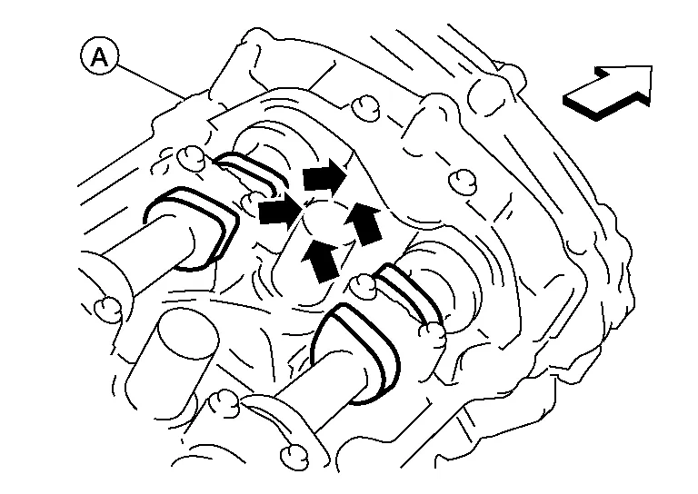
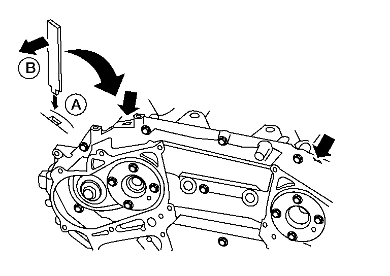
Install dowel pins (right and left) (A) into front timing chain case up to a point close to taper in order to shorten protrusion length.
NOTE:
Be sure to place the dowel pins in original hole locations in the front timing chain case (B).
Install the new front oil seal on the front timing chain case. Apply new engine oil to the oil seal edges.
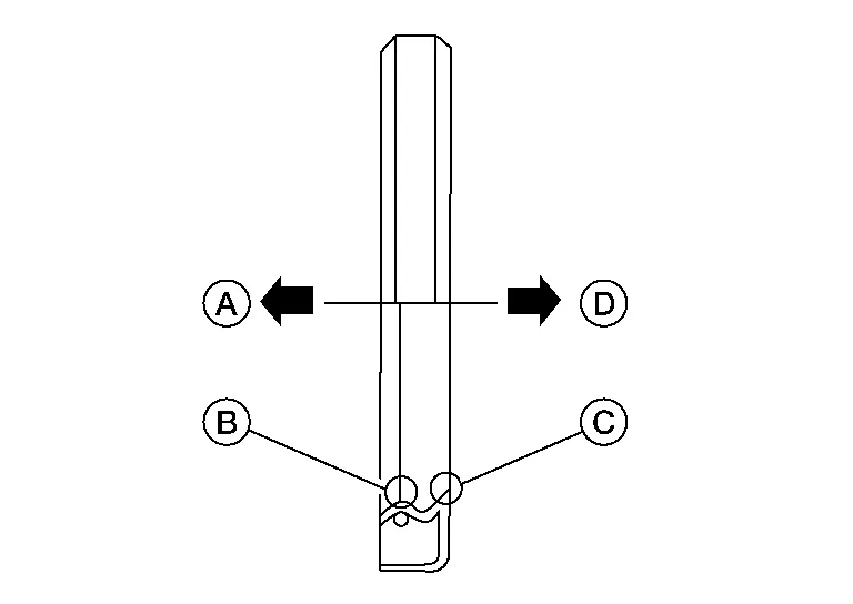
| (A) | : Engine inside |
| (B) | : Oil seal lip |
| (C) | : Dust seal lip |
| (D) | : Engine outside |
CAUTION:
Do not reuse front oil seal.
NOTE:
Install it so that each seal lip is oriented as shown.
Install the new front oil seal so that it becomes flush with the face with front timing chain case using Tool (A). Refer to Removal and Installation of Front Oil Seal.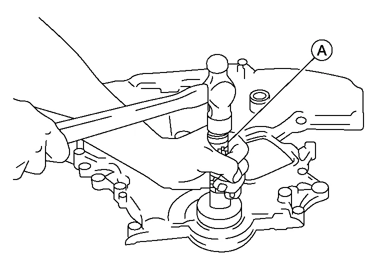
CAUTION:
Press fit straight and avoid causing burrs or tilting the oil seal.
NOTE:
Make sure the garter spring is in position and seal lip is not inverted.
| Tool number (A) | : — (J-37066) |
Install new O-rings (1) on rear timing chain case.
| (A) | : Bank 1 (RH) |
| (B) | : Bank 2 (LH) |
CAUTION:
Do not reuse O-rings.
Apply Silicone RTV Sealant to front timing chain case as shown.
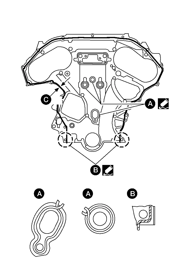
-
Use Genuine Silicone RTV Sealant, or equivalent. Refer to Recommended Chemical Products and Sealants.
-
Before installation, wipe off the protruding sealant.
-
(C): 2.6 - 3.6 mm (0.102 - 0.142 in) dia.
Install dowel pin on the front timing chain case into dowel pin hole in the rear timing chain case.
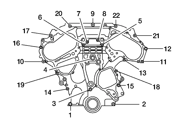
Loosely install the front timing chain case bolts.
| Bolt position | Bolt diameter |
| 1, 2 | : 8 mm (0.31 in) |
| 3 – 22 | : 6 mm (0.24 in) |
Tighten the front timing chain case bolts in the order as shown.
-
Retighten the front timing chain case bolts in the order as shown.
| Bolt position | Tightening specification |
| 1, 2 | : 28.4 N·m (2.9 kg-m, 21 ft-lb) |
| 3 – 22 | : 12.7 N·m (1.3 kg-m, 9 ft-lb) |
Install upper oil pan bolts (1) and (2) as shown. Refer to Removal and Installation (Upper Oil Pan).
| Engine front |
Install lower oil pan. Refer to Removal and Installation (Lower Oil Pan).
Install intake valve timing control solenoid valve covers as follows:Install new O-rings in shaft grooves.
CAUTION:
Do not reuse O-rings.
Being careful not to move O-rings from the installation grooves, align dowel pins on front timing chain case with the holes to install valve timing control covers. Tighten intake valve timing control solenoid valve cover bolts in numerical order as shown.
| (A) | : Bank 1 (RH) |
| (B) | : Bank 2 (LH) |
| (C) | : Dowel pin hole |
| Intake valve timing control solenoid valve cover bolts | : 11.3 N·m (1.2 kg-m, 8 ft-lb) |
Apply liquid gasket and install the water pump cover (if removed).
-
Use Genuine Silicone RTV Sealant or equivalent. Refer to Recommended Chemical Products and Sealants.
Install crankshaft pulley and tighten the bolt in two steps.
-
Lubricate thread and seat surface of the bolt with new engine oil.
-
Apply a paint mark for the second step of angle tightening.
| Step 1 | : 44.1 N·m (4.5 kg-m, 33 ft-lb) |
| Step 2 | : 84° - 90° degrees clockwise |
| Tool number (A) | : KV10112100 (BT-8653-A) |
Remove Tool and install the access plate.
| Tool number | : — (J-50288) |
CAUTION:
Do not damage the ring gear teeth, or the signal plate teeth behind the ring gear, when removing the Tool.
Rotate crankshaft pulley in normal direction (clockwise when viewed from front) to confirm it turns smoothly.
Installation of the remaining components is in the reverse order of removal.
INSPECTION AFTER INSTALLATION
-
Before starting engine, check oil/fluid levels including engine coolant and engine oil. If less than required quantity, fill to the specified level. Refer to Fluids and Lubricants.
-
Use procedure below to check for fuel leakage.
-
Turn ignition switch ON (with engine stopped). With fuel pressure applied to fuel piping, check for fuel leakage at connection points.
-
Start engine. With engine speed increased, check again for fuel leakage at connection points.
-
Run engine to check for unusual noise and vibration.
NOTE:
If hydraulic pressure inside timing chain tensioner drops after removal and installation, slack in the guide may generate a pounding noise during and just after engine start. However, this is normal. Noise will stop after hydraulic pressure rises.
-
Warm up engine thoroughly to make sure there is no leakage of fuel, exhaust gas, or any oils/fluids including engine oil and engine coolant.
-
Bleed air from passages in lines and hoses, such as in cooling system.
-
After cooling down engine, again check oil/fluid levels including engine oil and engine coolant. Refill to specified level, if necessary.
-
Summary of the inspection items:
Item Before starting engine Engine running After engine stopped Engine coolant Level Leakage Level Engine oil Level Leakage Level Transmission/transaxle fluid A/T and CVT Models Leakage Level/Leakage Leakage M/T Models Level/Leakage Leakage Level/Leakage Other oils and fluids* Level Leakage Level Fuel Leakage Leakage Leakage Exhaust gas — Leakage — *Power steering fluid, brake fluid, etc.
 Valve Timing Control
Exploded View
1.
Front timing chain case
2.
Valve timing control cover gasket (bank 1)
3.
O-ring
4.
O-ring
5.
Intake valve timing intermediate lock control solenoid valve (bank 1)
6...
 Timing Chain
Exploded View
1.
Timing chain tensioner (secondary) (bank 2)
2.
Internal chain guide
3.
Timing chain tensioner (secondary) (bank 1)
4.
Camshaft sprocket (bank 1) (EXH)
5...
Other information:
Nissan Murano (Z52) 2015-2024 Service Manual: Front Seat
Exploded View DRIVER SEAT WITH CLIMATE CONTROL 1. Headrest 2. Seat cushion trim 3. Seat cushion pad 4. Seatback assembly 5. Seat cushion outer finisher (RH) 6. Seat belt buckle 7. Seat cushion inner finisher [RH (front)] 8...
Nissan Murano (Z52) 2015-2024 Service Manual: Power Supply and Ground Circuit
Diagnosis Procedure CHECK ABS ACTUATOR AND ELECTRIC UNIT (CONTROL UNIT) IGNITION POWER SUPPLY Ignition switch OFF. Disconnect ABS actuator and electric unit (control unit) harness connector. Check the voltage between ABS actuator and electric unit (control unit) harness connector and ground...
Categories
- Manuals Home
- Nissan Murano Owners Manual
- Nissan Murano Service Manual
- Indicator lights
- Fuel recommendation
- Power Steering Fluid (PSF)
- New on site
- Most important about car
Fuel gauge

The gauge indicates the approximate fuel level in the tank.
The gauge may move slightly during braking, turning, acceleration, or going up or down hills.
The gauge needle returns to 0 (Empty) after the ignition switch is placed in the OFF position.