Nissan Murano: Seat :: Unit Disassembly and Assembly / Front Seat
DRIVER SEAT WITH CLIMATE CONTROL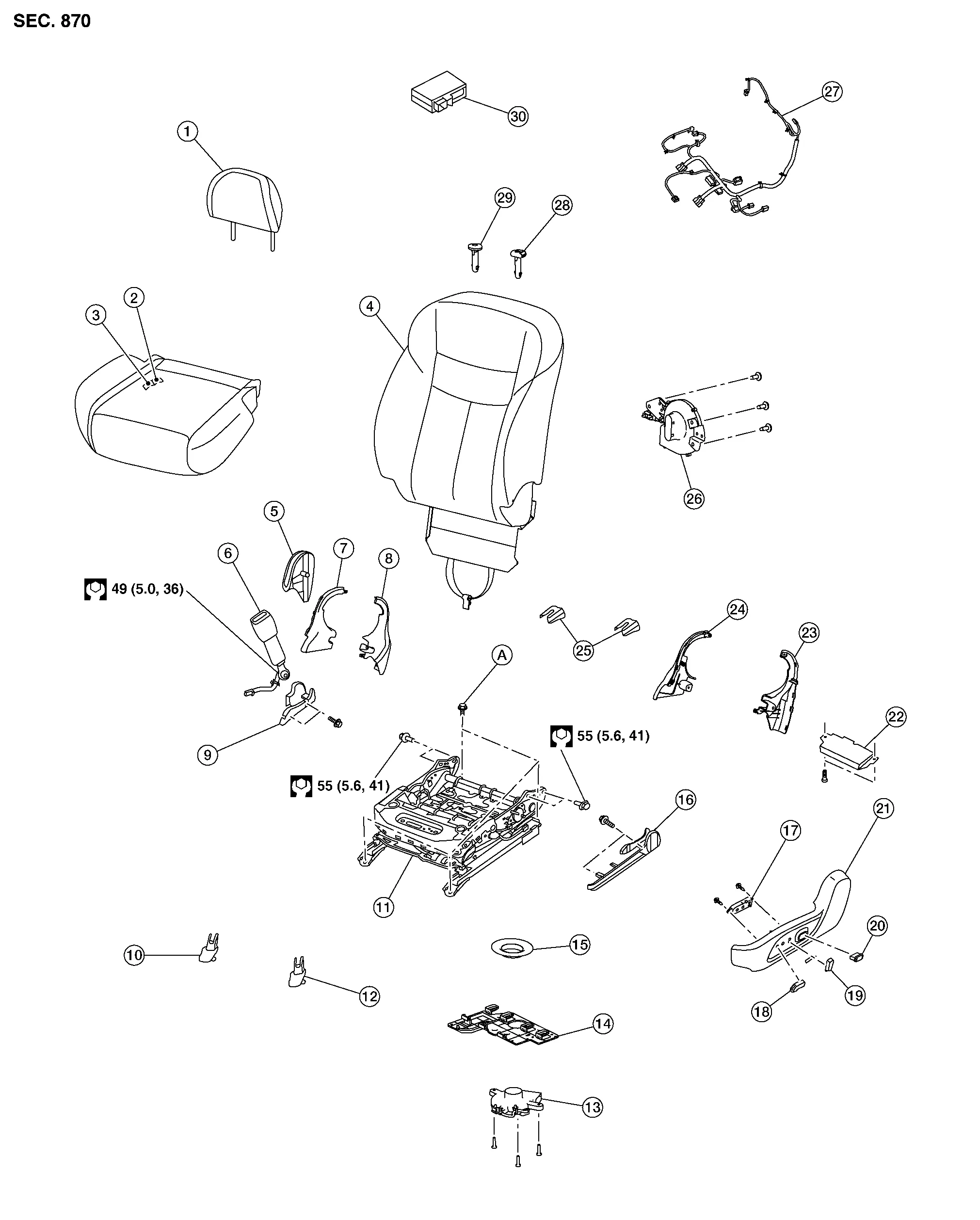
| 1. | Headrest | 2. | Seat cushion trim | 3. | Seat cushion pad |
| 4. | Seatback assembly | 5. | Seat cushion outer finisher (RH) | 6. | Seat belt buckle |
| 7. | Seat cushion inner finisher [RH (front)] | 8. | Seat cushion inner finisher [RH (rear)] | 9. | Slide finisher outer (RH) |
| 10. | Front slide finisher (RH) | 11. | Seat frame assembly | 12. | Front slide finisher (LH) |
| 13. | Seat cushion blower | 14. | Blower motor bracket | 15. | Blower motor nozzle |
| 16. | Slide finisher outer (LH) | 17. | Power seat switch | 18. | Seat slide knob |
| 19. | Seat recline knob | 20. | Lumbar support switch | 21. | Seat cushion outer finisher (LH) |
| 22. | Driver seat control unit | 23. | Seat cushion inner finisher [LH (rear)] | 24. | Seat cushion inner finisher [LH (front)] |
| 25. | Rear slide finisher | 26. | Seat back blower | 27. | Seat harness |
| 28. | Headrest holder (locked) | 29. | Headrest holder (free) | 30. | Climate controlled seat control unit |
| A. | Refer to Removal and Installation. |
DRIVER SEAT WITHOUT CLIMATE CONTROL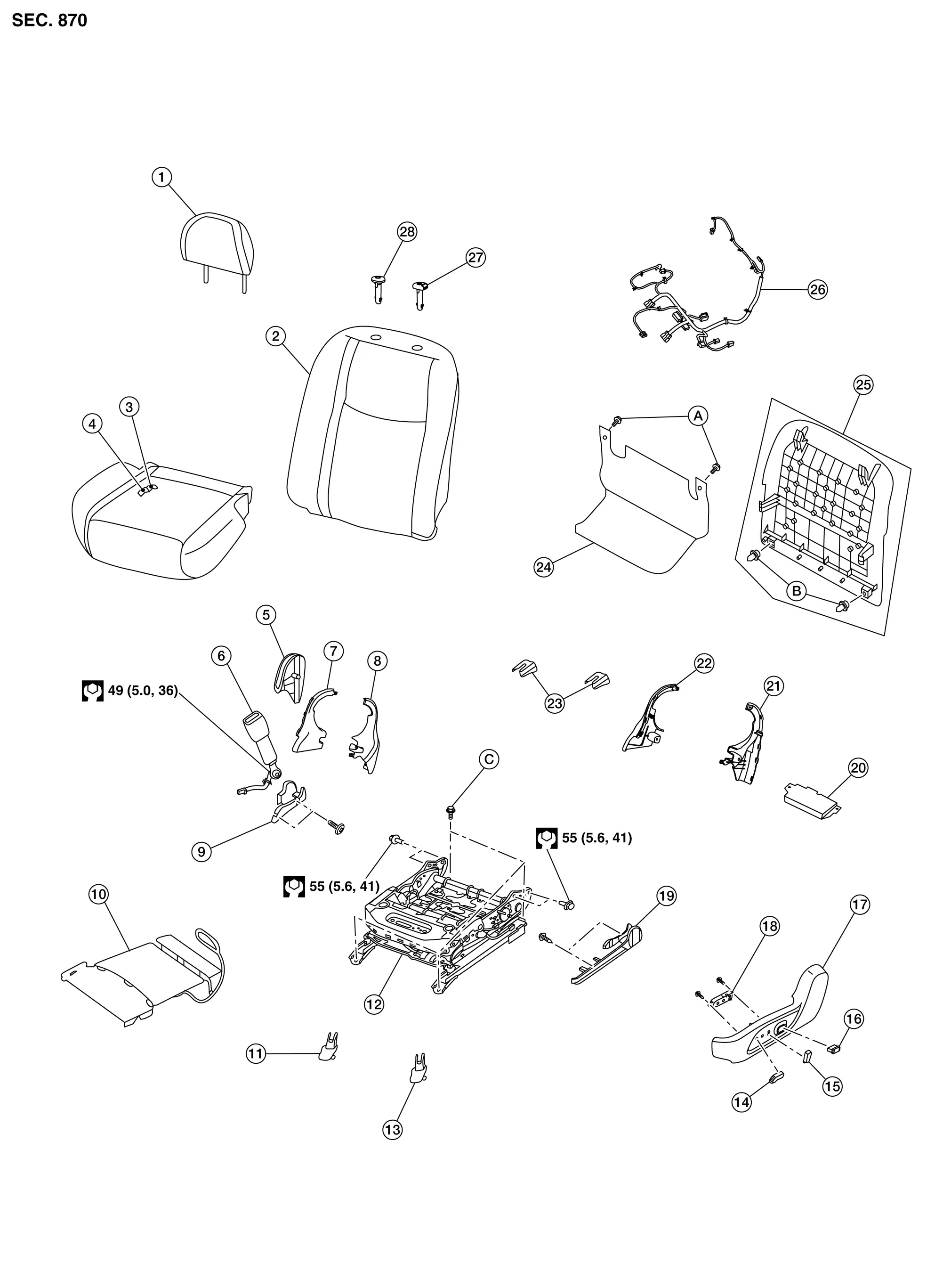
| 1. | Headrest | 2. | Seatback assembly | 3. | Seat cushion trim |
| 4. | Seat cushion pad | 5. | Seat cushion outer finisher (RH) | 6. | Seat belt buckle |
| 7. | Seat cushion inner finisher [RH (front)] | 8. | Seat cushion inner finisher [RH (rear)] | 9. | Slide finisher outer (RH) |
| 10. | Front seat heater (if equipped) | 11. | Front slide finisher (RH) | 12. | Seat frame assembly |
| 13. | Front slide finisher (LH) | 14. | Seat slide knob | 15. | Seat recline knob |
| 16. | Lumbar support switch | 17. | Seat cushion outer finisher (LH) | 18. | Power seat switch |
| 19. | Slide finisher outer (LH) | 20. | Driver seat control unit | 21. | Seat cushion inner finisher [LH (rear)] |
| 22. | Seat cushion inner finisher [LH (front)] | 23. | Rear slide finisher | 24. | Rear hinge cover |
| 25. | Seatback board | 26. | Seat harness | 27. | Headrest holder (locked) |
| 28. | Headrest holder (free) | A. | Rear hinge cover clips | B. | Seatback board clips |
| C. | Refer to Removal and Installation. |
DRIVER SEAT - MANUAL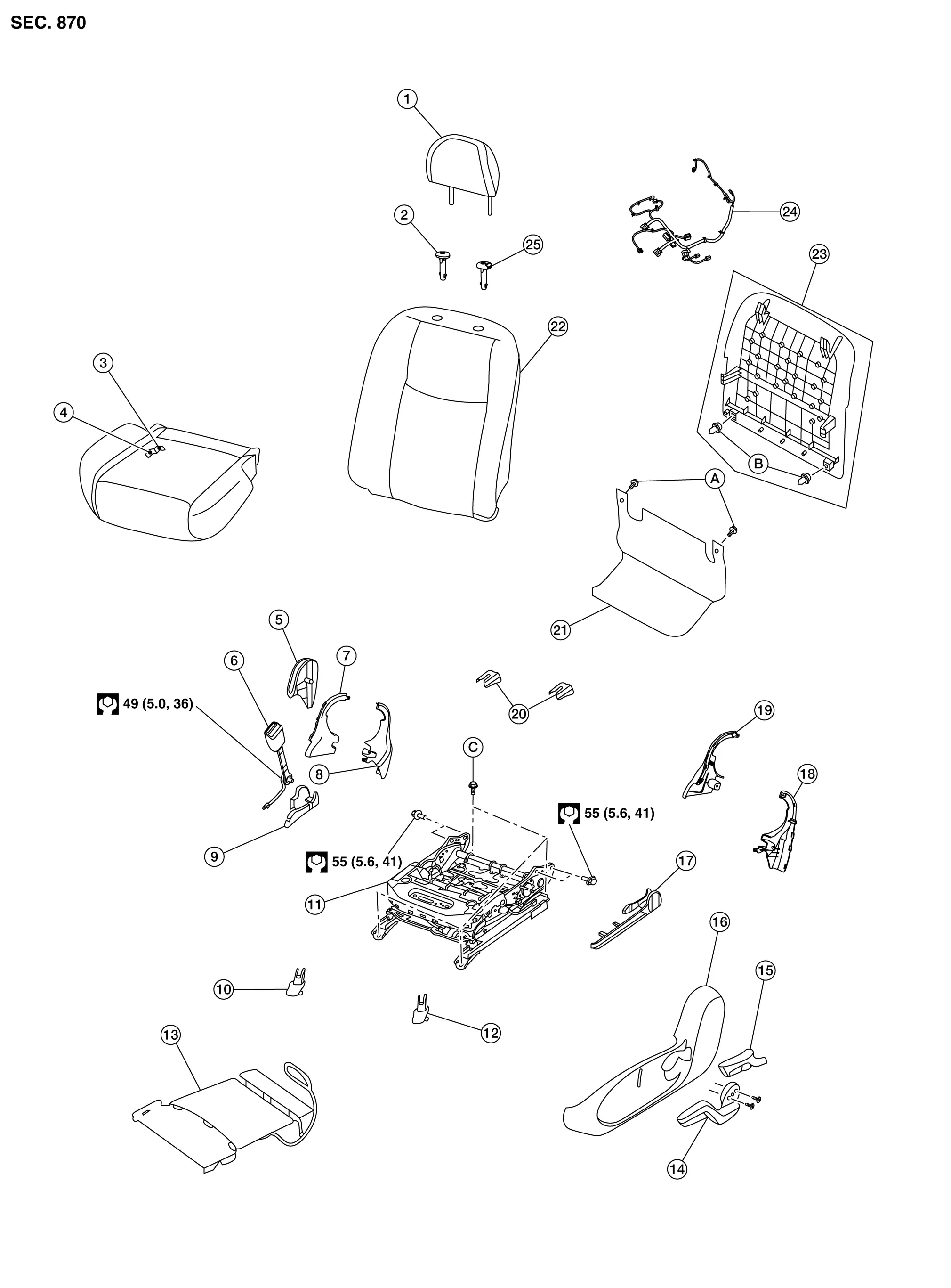
| 1. | Headrest | 2. | Headrest holder (free) | 3. | Seat cushion trim |
| 4. | Seat cushion pad | 5. | Seat cushion outer finisher (RH) | 6. | Seat belt buckle |
| 7. | Seat cushion inner finisher [RH (front)] | 8. | Seat cushion inner finisher [RH (rear)] | 9. | Slide finisher outer (RH) |
| 10. | Front slide finisher (RH) | 11. | Seat frame assembly | 12. | Front slide finisher (LH) |
| 13. | Front seat heater (if equipped) | 14. | Lift lever | 15. | Recline lever finisher |
| 16. | Seat cushion outer finisher (LH) | 17. | Slide finisher outer (LH) | 18. | Seat cushion inner finisher [LH (rear)] |
| 19. | Seat cushion inner finisher [LH (front)] | 20. | Rear slide finisher | 21. | Rear hinge cover |
| 22. | Seatback assembly | 23. | Seatback board | 24. | Seat harness |
| 25. | Headrest holder (locked) | A. | Rear hinge cover clips | B. | Seatback board clips |
| C. | Refer to Removal and Installation. |
PASSENGER SEAT WITH CLIMATE CONTROL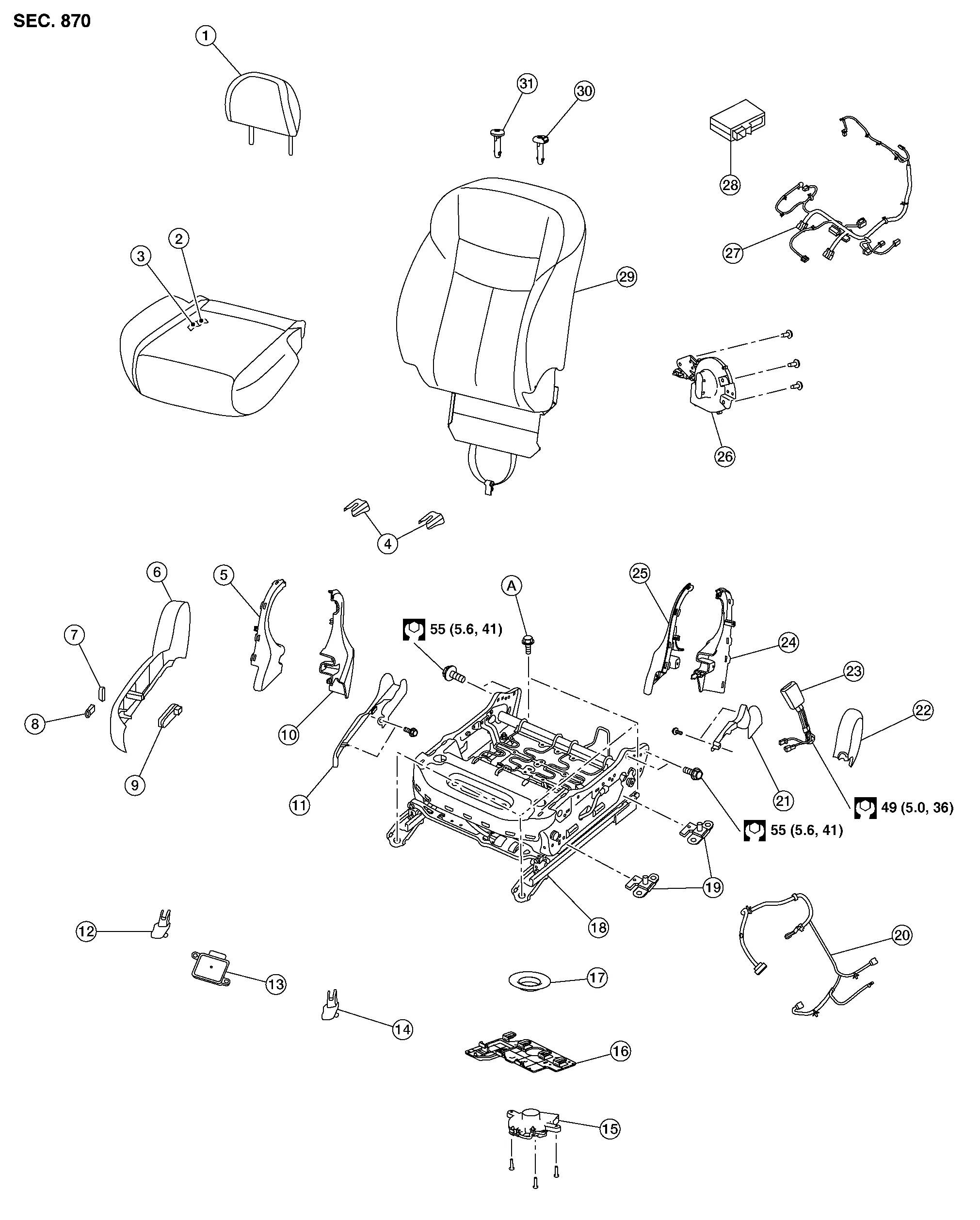
| 1. | Headrest | 2. | Seat cushion trim | 3. | Seat cushion pad |
| 4. | Rear slide finisher | 5. | Seat cushion inner finisher [RH (front)] | 6. | Seat cushion outer finisher (RH) |
| 7. | Seat recline knob | 8. | Seat slide knob | 9. | Power seat switch |
| 10. | Seat cushion inner finisher [RH (rear)] | 11. | Slide finisher outer (RH) | 12. | Front slide finisher (RH) |
| 13. | Occupant Classification System control unit | 14. | Front slide finisher (LH) | 15. | Seat cushion blower |
| 16. | Blower motor bracket | 17. | Blower motor nozzle | 18. | Seat frame assembly |
| 19. | Occupant Classification System sensor | 20. | Occupant Classification System harness | 21. | Slide finisher outer (LH) |
| 22. | Seat cushion outer finisher (LH) | 23. | Seat belt buckle | 24. | Seat cushion inner finisher [LH (rear)] |
| 25. | Seat cushion inner finisher [LH (front)] | 26. | Seat back blower | 27. | Seat harness |
| 28. | Climate controlled seat control unit | 29. | Seatback assembly | 30. | Headrest holder (locked) |
| 31. | Headrest holder (free) | A. | Refer to Removal and Installation. |
PASSENGER SEAT WITHOUT CLIMATE CONTROL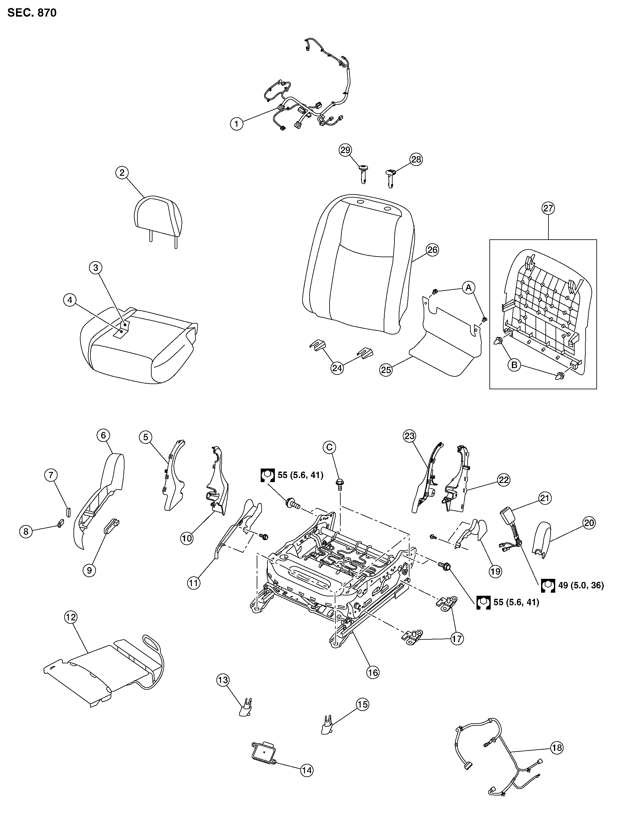
| 1. | Seat harness | 2. | Headrest | 3. | Seat cushion trim |
| 4. | Seat cushion pad | 5. | Seat cushion inner finisher [RH (front)] | 6. | Seat cushion outer finisher (RH) |
| 7. | Seat recline knob | 8. | Seat slide knob | 9. | Power seat switch |
| 10. | Seat cushion inner finisher [RH (rear)] | 11. | Slide finisher outer (RH) | 12. | Front seat heater (if equipped) |
| 13. | Front slide finisher (RH) | 14. | Occupant Classification System control unit | 15. | Front slide finisher (LH) |
| 16. | Seat frame assembly | 17. | Occupant Classification System sensor | 18. | Occupant Classification System harness |
| 19. | Slide finisher outer (LH) | 20. | Seat cushion outer finisher (LH) | 21. | Seat belt buckle |
| 22. | Seat cushion inner finisher [LH (rear)] | 23. | Seat cushion inner finisher [LH (front)] | 24. | Rear slide finisher |
| 25. | Seat hinge cover | 26. | Seatback assembly | 27. | Seatback board |
| 28. | Headrest holder (locked) | 29. | Headrest holder (free) | A. | Rear hinge cover clips |
| B. | Seatback board clips | C. | Refer to Removal and Installation. |
PASSENGER SEAT - MANUAL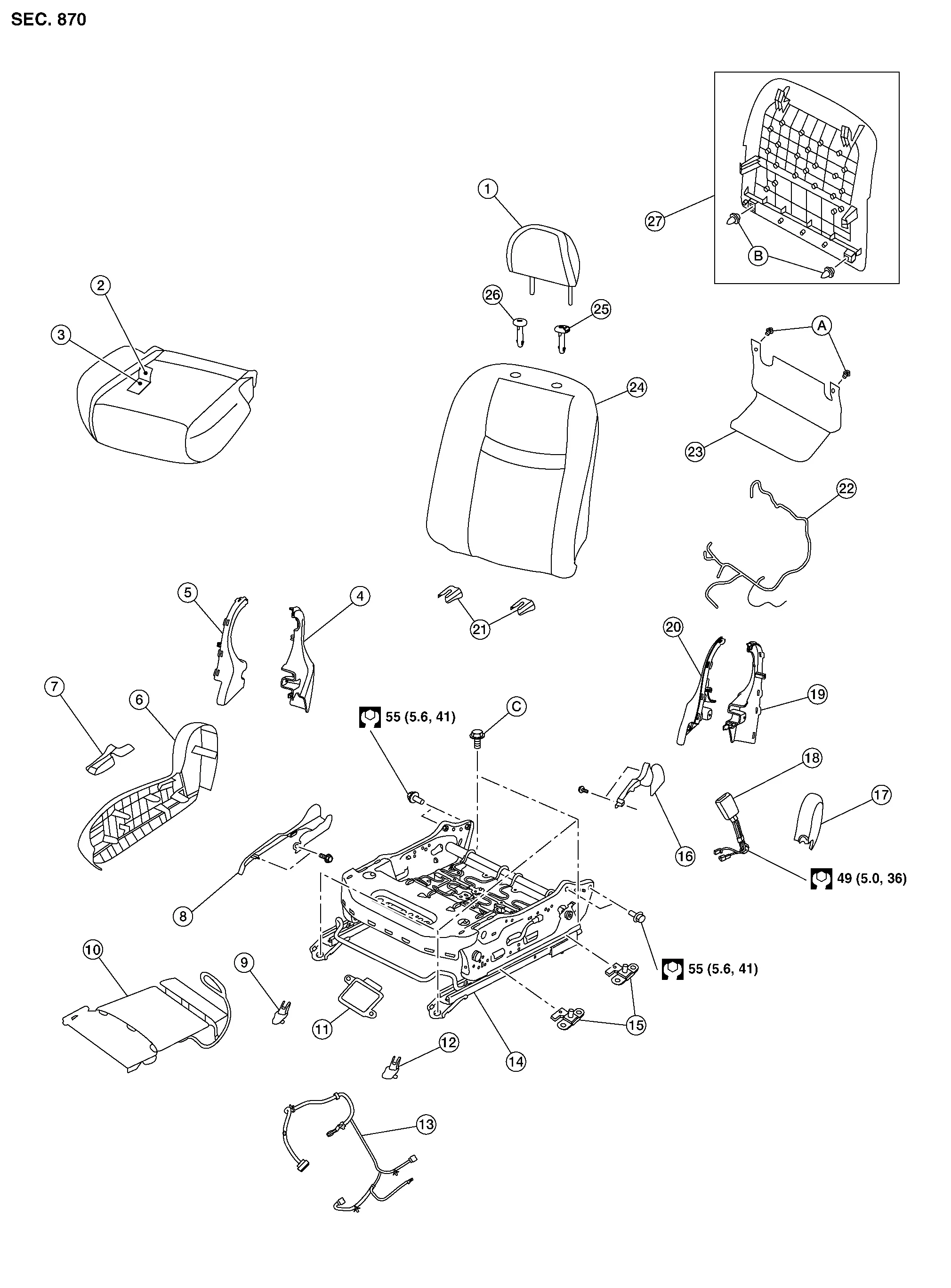
| 1. | Headrest | 2. | Seat cushion trim | 3. | Seat cushion pad |
| 4. | Seat cushion inner finisher [RH (rear)] | 5. | Seat cushion inner finisher [RH (front)] | 6. | Seat cushion outer finisher (RH) |
| 7. | Front slide finisher (RH) | 8. | Slide finisher outer (RH) | 9. | Front slide finisher (RH) |
| 10. | Front seat heater (if equipped) | 11. | Occupant Classification System control unit | 12. | Front slide finisher (LH) |
| 13. | Occupant Classification System harness | 14. | Seat frame assembly | 15. | Occupant Classification System sensor |
| 16. | Slide finisher outer (LH) | 17. | Seat cushion outer finisher (LH) | 18. | Seat belt buckle |
| 19. | Seat cushion inner finisher [LH (rear)] | 20. | Seat cushion inner finisher [LH (front)] | 21. | Rear slide finisher |
| 22. | Seat harness | 23. | Seat hinge cover | 24. | Seatback assembly |
| 25. | Headrest holder (locked) | 26. | Headrest holder (free) | 27. | Seatback board |
| A. | Rear hinge cover clips | B. | Seatback board clips | C. | Refer to Removal and Installation. |
DISASSEMBLY
WARNING:
Do not leave any objects (screwdrivers, tools, etc.) on the seat during seatback repair. It can lead to personal injury if the side air bag module should accidentally deploy.
CAUTION:
-
Before servicing, place the ignition switch in the OFF position, disconnect both battery terminals then wait at least three minutes.
-
Always work from the side or back of the seatback, do not work in front of seat.
-
Do not use air tools or electric tools for servicing the seat assembly.
-
Do not insert any objects into the side air bag module.
-
Do not attempt to disassemble the side air bag module.
-
Do not expose the side air bag module to temperatures exceeding 90°C (194°F).
-
Do not expose the side air bag module to any oil, grease, detergent or water.
-
During disassembly, do not damage the seatback board, connectors, retainers, clips, module harness or the side air bag module.
 NOTE:
NOTE:
-
If the vehicle has been involved in a collision and the side air bag module has deployed, the seatback must be replaced.
-
Driver side shown; passenger side similar.
Remove front seat. Refer to Removal and Installation.
Remove the seat hinge cover (if equipped). Refer to Seat Hinge Cover.
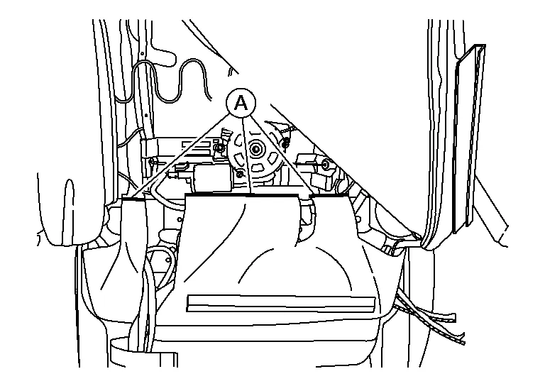
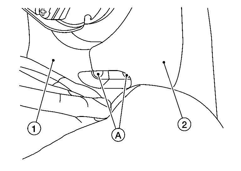
For models with climate controlled seats, perform the following steps:Release seatback J-hook (A) and position seatback flap (B) aside.
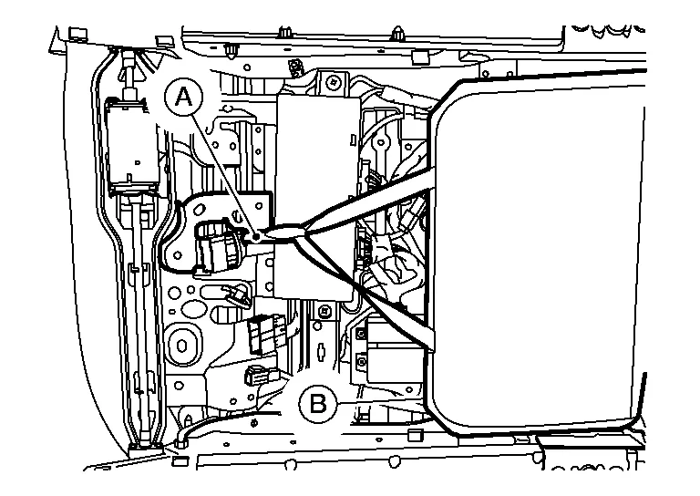
NOTE:
Driver side shown; passenger side similar.
Release seatback zippers (A), and release J-retainer (B) then position upper seatback trim aside.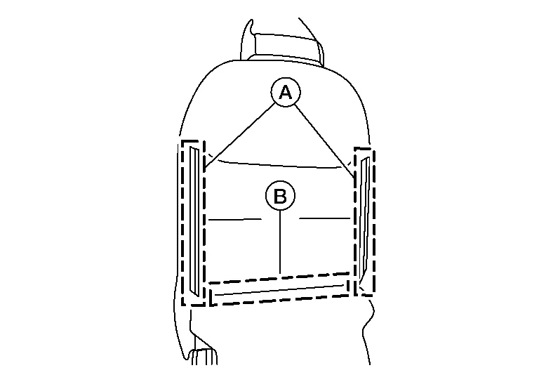
Press the headrest holder lock button and lift headrest up to remove from the seat back assembly.
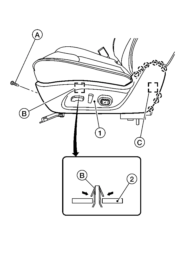
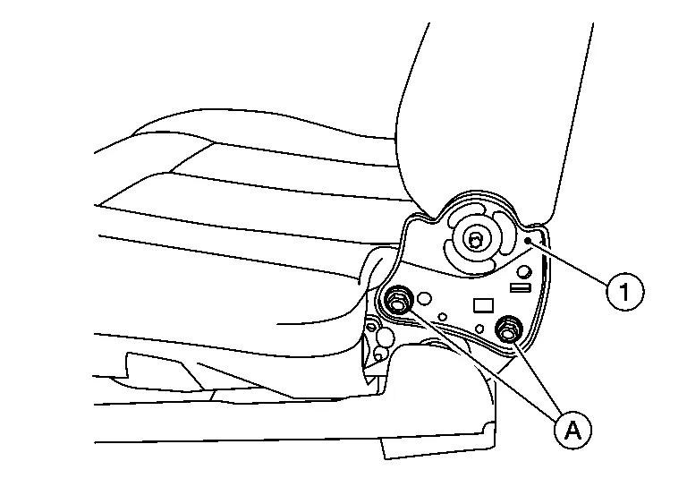
Remove the seat cushion outer finisher (LH) (1).For power seat:
-
Remove screw (A).
-
Release metal clip (B) from the seat frame assembly (2), as shown.
 : Metal clip
 -
Release pawls and metal clip (C), then remove.
 : Pawl: Metal clip
 -
Disconnect the harness connectors from the power seat switch and the lumbar support switch (if equipped).
-
Release pawl and remove recline lever (1) as shown (
 ).
).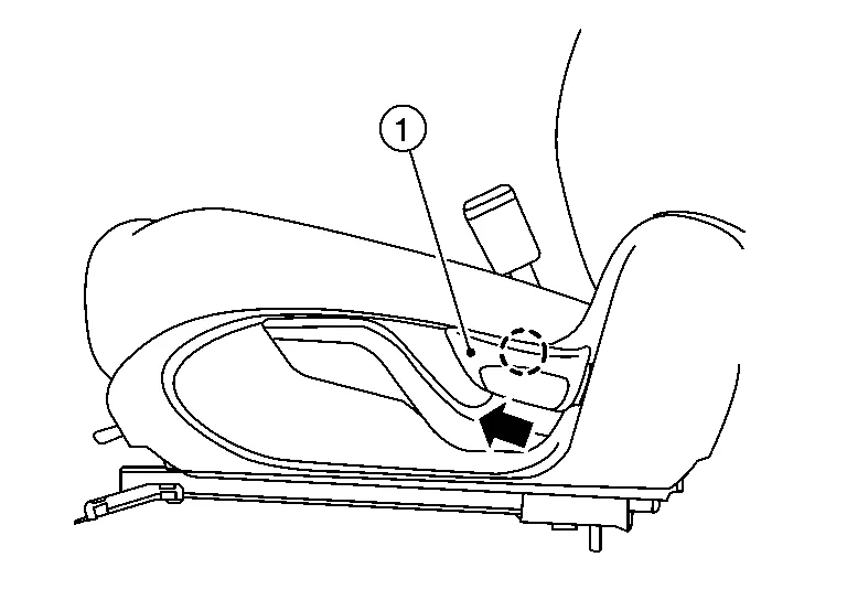 : Pawl
 -
Remove screws and lift lever.
-
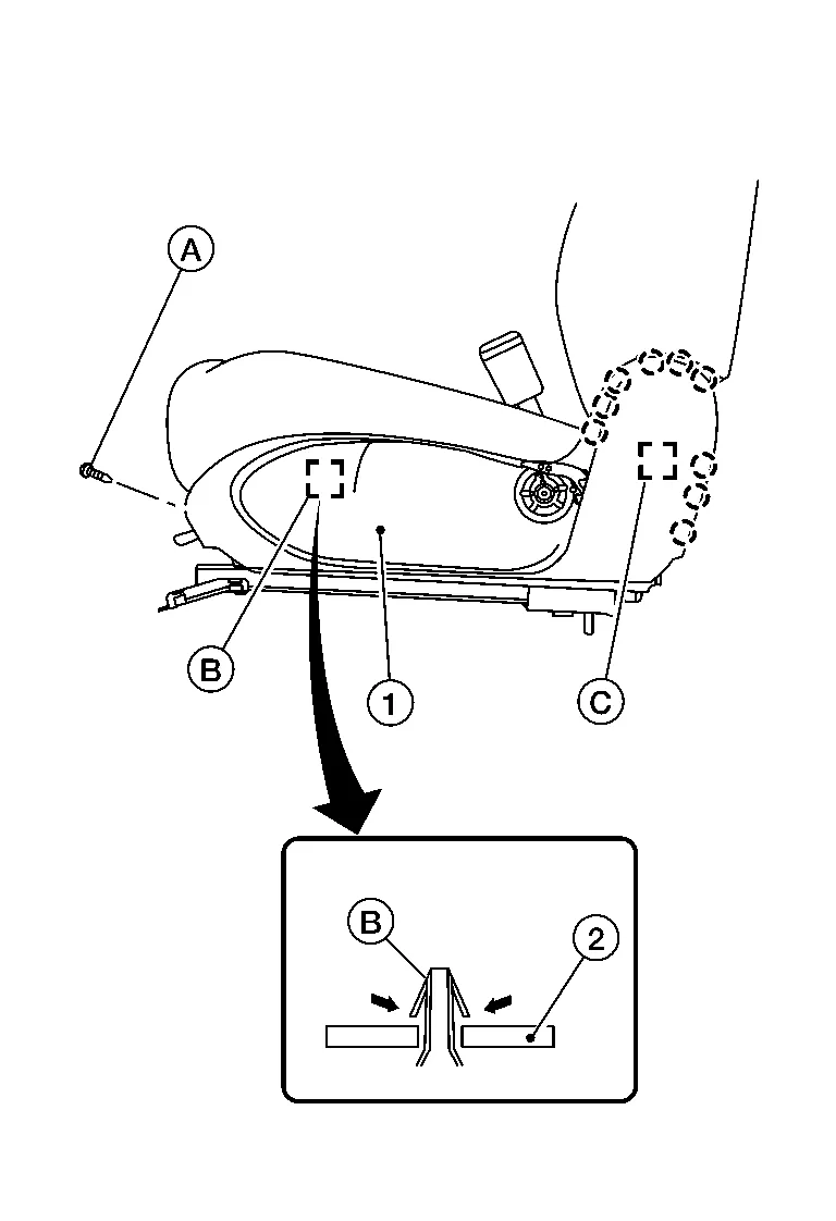
Release metal clip (B) from the seat frame assembly (1), as shown.
: Metal clip -
Release pawls and metal clip (C), then remove.
: Pawl: Metal clip
Release pawls and metal clip, and remove the seat cushion outer finisher (RH).
: Pawl
: Metal clip
Unclip the side air bag module harness from the seat frame assembly.
NOTE:
Take note of harness routing and attachment location for correct installation.
Disconnect the harness connector from the lumbar support motor (if equipped) and unclip the harness from the seatback assembly.
NOTE:
Take note of harness routing and attachment location for correct installation.
Disconnect the harness connector for the seatback heater (if equipped).
NOTE:
Take note of harness routing and attachment location for correct installation.
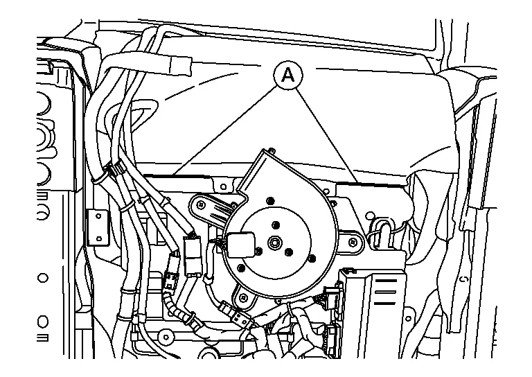
Disconnect the harness connector from the seat back blower (if equipped) and unclip the harness from the seatback assembly.
NOTE:
Take note of harness routing and attachment location for correct installation.
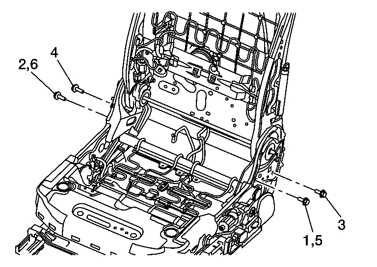
Reposition seat cushion assembly and remove screws (A), then remove the seat cushion inner finisher (LH/RH) (front) (1) and seat cushion inner finisher (LH/RH) (rear) (2).
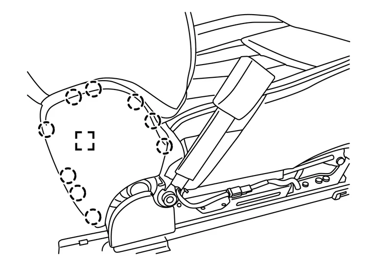
Remove bolts (A) on both sides of the seatback assembly (1).
ASSEMBLY
-
Install all seatback assembly bolts and tighten evenly in the order shown.
-
Tighten the seatback assembly bolts to specification. Refer to Exploded View.
CAUTION:
-
Always route side air bag module harness in original location. Replace any deformed or damaged clips with same type and color. Always install clips in the original location in the harness.
-
After work is completed, check that no system malfunction is detected causing the air bag warning lamp to illuminate.
-
If a malfunction is detected by the air bag warning lamp after repair or replacement of the malfunction parts, perform the SRS final check. Refer to SRS Final Check.
DISASSEMBLY
WARNING:
Do not leave any objects (screwdrivers, tools, etc.) on the seat during seat cushion repair. It can lead to personal injury if the side air bag module should accidentally deploy.
CAUTION:
-
Before servicing, place the ignition switch in the OFF position, disconnect both battery terminals and wait at least three minutes.
-
Always work from the side or back of the seatback assembly, do not work in front of seat.
-
Do not use air tools or electric tools for servicing the seat assembly.
NOTE:
Front seat (LH) shown; front seat (RH) similar.
Remove the front seat. Refer to Removal and Installation.
Remove the seat cushion outer finisher (LH) (1).For power seat:
-
Remove screw (A).
-
Release metal clip (B) from the seat frame assembly (2), as shown.
: Metal clip -
Release pawls and metal clip (C), then remove.
: Pawl: Metal clip -
Disconnect the harness connectors from the power seat switch and the lumbar support switch (if equipped).
-
Release pawl and remove recline lever (1) as shown (
).: Pawl -
Remove screws and lift lever.
-
Release metal clip (B) from the seat frame assembly (1), as shown.
: Metal clip -
Release pawls and metal clip (C), then remove.
: Pawl: Metal clip
Release pawls and metal clip and remove the seat cushion outer finisher (RH).
: Pawl
: Metal clip
For models with climate controlled seats, release seatback J-hook (A) and position seatback flap (B) aside.
NOTE:
Driver side shown; passenger side similar.
Remove the seat cushion from the seat frame assembly using the following procedure.Release the rear J-hooks.
-
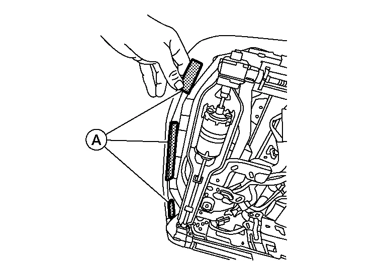
For models with climate controlled seats, release the rear J-hooks (A) from the seat frame assembly.
-
For models without climate controlled seats, release the rear hinge cover J-hooks (A) from the seat frame assembly (1).
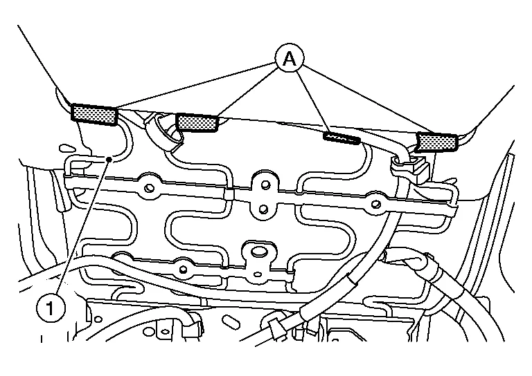
NOTE:
Take note of harness routing and attachment location for correct installation.
Remove the seat cushion trim and seat cushion pad as an assembly from the seat frame assembly.Remove the hog rings and separate the seat cushion trim and seat cushion pad.
NOTE:
Remove all pieces of hog rings and discard them.
ASSEMBLY
Assembly is in the reverse order of disassembly.
-
Install new hog rings on the seat cushion trim in original positions.

-
Use only one hog ring in each designated location.
-
Make sure hog rings are correctly fastened around both the seat cushion trim and seat cushion pad wires.
-
Use NISSAN standard hog rings and tools to assemble.
-
Make sure hook fastener is pressed into place after seat cushion trim is assembled.
-
Smooth out all wrinkles during assembly.
CAUTION:
-
Always route side air bag module harness in original location. Replace any deformed or damaged clips with same type and color. Always install clips in the original location in the harness.
-
After work is completed, check that no system malfunction is detected causing the air bag warning lamp to illuminate.
-
If a malfunction is detected by the air bag warning lamp after repair or replacement of the malfunction parts, perform the SRS final check. Refer to SRS Final Check.

 Second Row Seat
Exploded View
LH SEAT — With Heated Seats 1.
Seatback board
2.
Seat cushion trim
3.
Seat cushion pad (with heated seats)
4.
Seat cushion link cover (RH)
5...
Other information:
Nissan Murano (Z52) 2015-2024 Owners Manual: Stopping the vehicle
Safelymove the vehicle off the road and away from traffic. Turn on the hazard warning flashers. Park on a level surface and apply the parking brake. Move the shift lever to P (Park). Turn off the engine. Raise the hood to warn other traffic and to signal professional road assistance personnel that you need assistance...
Nissan Murano (Z52) 2015-2024 Service Manual: System
System Description SYSTEM DIAGRAMAudio Unit Input Signal (AV Communication)Transmit unitSignal name Combination meter Steering switch signal Audio Unit Input Signal (CAN Communication)Transmit unitSignal name BCM Door switches state signal Combination meter Nissan Murano Vehicle speed signal Hand brake switch signal ECM Engine RPM Signal IPDM E/R Battery voltage signal AUDIO SYSTEMThe audio system consists of the following components: Audio unit Instrument panel tweeters Front door speakers Rear door speakers Front auxiliary input jacks Front auxiliary input jacks control unit Microphone Steering switches Combination meter Combination switch (spiral cable) Accessory relay-2 Antenna base (AM/FM antenna, antenna amp...
Categories
- Manuals Home
- Nissan Murano Owners Manual
- Nissan Murano Service Manual
- Shift lock release
- Checking engine oil level
- Passenger compartment
- New on site
- Most important about car
Fuel gauge

The gauge indicates the approximate fuel level in the tank.
The gauge may move slightly during braking, turning, acceleration, or going up or down hills.
The gauge needle returns to 0 (Empty) after the ignition switch is placed in the OFF position.