Nissan Murano: Audio, Visual & Navigation System :: Telematics System / Ecu Diagnosis Information. Tcu
 NOTE:
NOTE:
The following table includes information (items) inapplicable to this Nissan Murano vehicle. For information (items) applicable to this vehicle, refer to CONSULT display items.
| Monitor Item | Condition | Value/Status |
|---|---|---|
| HF TYPE | Ignition switch ON | BT |
| AUDIO UNIT TYPE | NAVI | |
| CALL SWITCH TYPE | SOS | |
| SPEAKER TYPE | INDRCT | |
| ZONE | USA | |
| CHANNEL | NISSAN | |
| CAN COMM | GEN.3 | |
| AV COMM | ENABLE | |
| K-LINE | DISABLE | |
| Nissan Murano Vehicle TYPE | ENG | |
| ECHO CANCEL | TYPE1 | |
| NOISE CANCEL | TYPE1 | |
| TCU STANDBY TIME | Set at 14 days (default) | 14DAYS |
| Set at 2 days | 2DAYS | |
| Set at 30 days | 30DAYS | |
| No setting | NON | |
| SENSOR ANGLE X | Ignition switch ON | 4.0 |
| SENSOR ANGLE Y | 4.0 | |
| SENSOR ANGLE Z | 4.0 | |
| SVTB | DISABLE | |
| REMOTE DOOR LOCK | DISABLE | |
| REMOTE HORN & LAMP | DISABLE | |
| REMOTE START | DISABLE | |
| NAD OUTPUT STATUS | When TCU activation is ON | On |
| When TCU activation is OFF | Off | |
| ACN COMM SEQUENCE LOG | — | — |
| SOS COMM SEQUENCE LOG | — | — |
| SOS SW | SOS switch pressed | On |
| SOS switch released | Off |
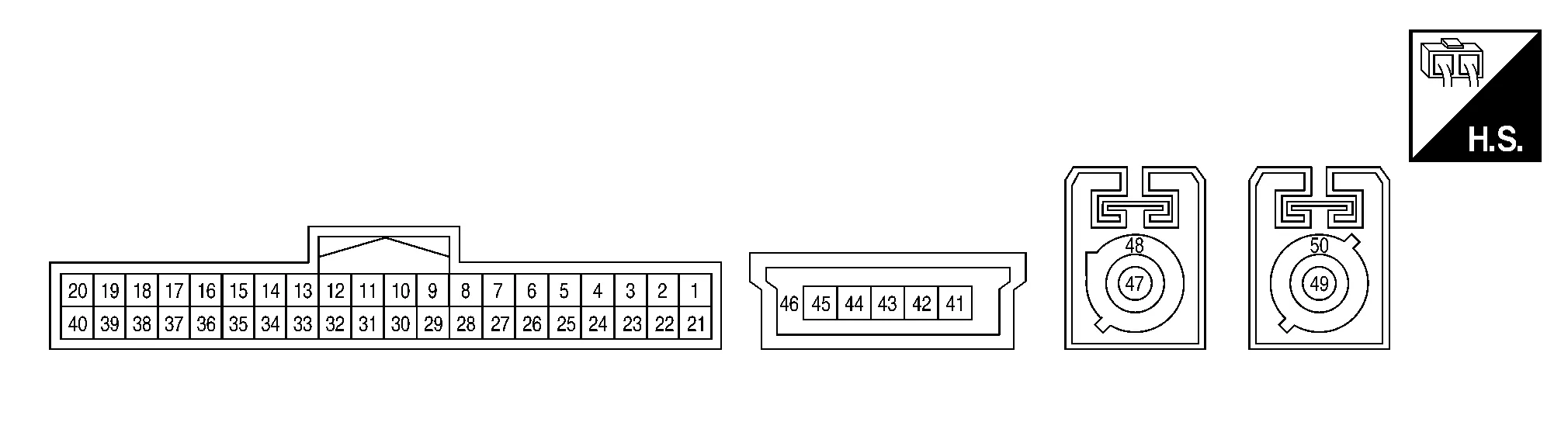
TERMINAL LAYOUT
PHYSICAL VALUES
|
Terminal (Wire color) | Description | Condition |
Reference value (Approx.) | ||
|---|---|---|---|---|---|
| + | – | Signal name | Input/Output | ||
|
1 (BG) |
Ground | Battery power supply | Input | Ignition switch OFF | Battery Voltage |
|
2 (P) |
Ground | ACC power supply | Input | Ignition switch ACC | Battery Voltage |
|
3 (P) |
Ground | ACC output | Output | Ignition switch ACC | Battery Voltage |
|
5 (BG) |
Ground | SOS switch LED signal | Input | Ignition switch ON | 5.0 V |
|
6 (L) |
— | CAN-High | Input/Output | — | — |
|
7 (P) |
— | CAN-Low | Input/Output | — | — |
|
10 (LG) |
Ground | Ignition signal | Input | Ignition switch ON | 12.0 V |
|
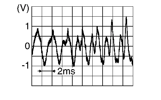
12 (B) |
Ground | Microphone output signal | Output |
Ignition switch ON
|
|
|
17 (B) |
Ground | Microphone signal | Input |
Ignition switch ON
|
|
|
18 (W) |
Ground | Microphone VCC | Output | Ignition switch ON | 4.72 V |
|
26 (SB) |
— | AV communication high | Input/Output | — | — |
|
27 (LG) |
— | AV communication low | Input/Output | — | — |
|
28 (B) |
— | Ground | — | — | — |
|
29 (B) |
— | Ground | — | — | — |
|
31 (W) |
32 (B) |
Sound signal (+) | Input |
Ignition switch ON
|
|
|
32 (B) |
— | Sound signal (−) | — | — | — |
|
37 (P) |
Ground | SOS call switch signal | Input |
Ignition switch ON
|
0 V |
| Except for above | 5.0 V | ||||
|
41 (B) |
— | USB ground | — | — | — |
|
43 (G) |
— | USB D+ signal | — | — | — |
|
44 (W) |
— | USB D- signal | — | — | — |
|
45 (R) |
— | V BUS signal | — | — | — |
|
46 (Shield) |
— | USB shield | — | — | — |
|
47 (B) |
Ground | TEL antenna signal | Input | TEL antenna disconnected. | 5.0 V |
|
48 (Shield) |
— | TEL antenna shield | — | — | — |
|
49 (B) |
Ground | GPS antenna signal | Input | GPS antenna disconnected. | 5.0 V |
|
50 (Shield) |
— | GPS antenna shield | — | — | — |
If a malfunction occurs in the telematics system, TCU performs fail-safe activation according to the detected malfunction.
| Detection item | Telematics system operation in fail-safe mode | DTC |
|---|---|---|
| Air-bag connection |
|
U1A10 |
| CAN communication |
|
U1000 |
| TEL antenna |
|
U1A06 |
| GPS antenna |
|
U1A09 U1A0A |
| USB communication |
|
B13D9 |
| TCU | Telematics system function stops. |
B1310 B130D B2EF0 U1010 U1A01 U1A02 |
|
U1A03 U1A11 |
|
|
Telematics switch (SOS call switch) |
|
B2E33 U1A0E |
| Microphone |
|
U1A0B |
| VIN | Telematics service does not function. | U1A04 |
If multiple DTCs are detected simultaneously, check them one by one depending on the following DTC inspection priority chart.
| Priority | Detected items (DTC) |
|---|---|
| 1 | U1A04: VIN UNFINISHED |
| 2 |
|
| 3 |
|
| DTC | Display contents of CONSULT | Reference |
|---|---|---|
| B130C | TCU pairing error | DTC Description |
| B130D | TEL LINE OUT ERROR | DTC Description |
| B1310 | TCU TEMPERATURE ERROR | DTC Description |
| B13D9 | USB CONNECTION | DTC Description |
| B2E33 | ECALL BUTTON | DTC Description |
| B2EF0 | INTERNAL BATTERY | DTC Description |
| U1000 | CAN COMM CIRCUIT | DTC Description |
| U1010 | CONTROL UNIT(CAN) | DTC Description |
| U1A01 | INTERNAL ERROR (TCU) | DTC Description |
| U1A02 | TEL COMMUNICATION MODULE | DTC Description |
| U1A03 | SIM CARD | DTC Description |
| U1A04 | VIN UNFINISHED | DTC Description |
| U1A05 | USB COMM | DTC Description |
| U1A06 | TEL ANTENNA ERROR | DTC Description |
| U1A09 | GPS ANTENNA CONN | DTC Description |
| U1A0A | GPS MODULE COMM | DTC Description |
| U1A0B | MIC IN CONN | DTC Description |
| U1A0E | SOS SWITCH ON STUCK | DTC Description |
| U1A10 | AIRBAG SIGNAL | DTC Description |
| U1A11 | TEL MUTE OUTPUT SIGNAL NO CONN | DTC Description |
 Diagnosis System (tcu)
CONSULT Function
APPLICABLE ITEMSCONSULT performs the following functions via communication with the TCU. Direct Diagnostic Mode Description
ECU Identification
The TCU part number and various ID numbers are displayed...

Other information:
Nissan Murano (Z52) 2015-2024 Service Manual: Engine Mechanical :: Precaution. Precautions
Precaution for Supplemental Restraint System (SRS) "AIR BAG" and "SEAT BELT PRE-TENSIONER" The Supplemental Restraint System such as “AIR BAG” and “SEAT BELT PRE-TENSIONER”, used along with a front seat belt, helps to reduce the risk or severity of injury to the driver and front passenger for certain types of collisions...
Nissan Murano (Z52) 2015-2024 Owners Manual: Fuel-filler cap
WARNING Gasoline is extremely flammable and highly explosive under certain conditions. You could be burned or seriously injured if it is misused or mishandled. Always stop the engine and do not smoke or allow open flames or sparks near the vehicle when refueling...
Categories
- Manuals Home
- Nissan Murano Owners Manual
- Nissan Murano Service Manual
- Turning the AEB system on/off
- Settings
- All-Wheel Drive (AWD) (if so equipped)
- New on site
- Most important about car
Unfastening the seat belts. Checking seat belt operation
Unfastening the seat belts

To unfasten the seat belt, press the button
on the buckle  . The seat belt
automatically
retracts.
. The seat belt
automatically
retracts.