Nissan Murano: Unit Disassembly and Assembly / Drive Pinion

 |
Oil seal |  |
Transfer cover |  |
Filler plug |
 |
Gasket |  |
Drain plug |  |
Oil seal |
 |
O-ring |  |
Ring gear bearing adjusting shim (transfer cover side) |  |
Ring gear bearing (transfer cover side) |
 |
Drive shaft oil seal |  |
Ring gear shaft |  |
Ring gear bearing (transfer case side) |
 |
Ring gear bearing adjusting shim (transfer case side) |  |
Ring gear |  |
Baffle plate |
 |
Transfer case |  |
Plug |  |
O-ring |
 |
Oil seal |  |
Dowel pin |  |
Drive pinion |
 |
Drive pinion adjusting shim |  |
O-ring |  |
Pinion bearing assembly |
 |
Oil seal |  |
Dust cover |  |
Companion flange |
 |
Pinion lock nut | ||||
 |
Oil seal lip |  |
Comply with the assembly procedure when tightening. Refer to Disassembly and Assembly. | ||
 : N·m (kg-m, in-lb) : N·m (kg-m, in-lb) |
|||||
 : N·m (kg-m, ft-lb) : N·m (kg-m, ft-lb) |
|||||
 : Always replace after every disassembly. : Always replace after every disassembly. |
|||||
 : Apply gear oil. : Apply gear oil. |
|||||
| *: Apply anti-corrosive oil. |
|||||
 : Apply multi-purpose grease. : Apply multi-purpose grease. |
|||||
 : Select with proper thickness. : Select with proper thickness. |
|||||
DISASSEMBLY
Remove pinion bearing assembly mounting bolts.

Lightly tap companion flange with a plastic hammer to remove drive pinion assembly .
Remove the O-ring from pinion bearing.
Remove the pinion lock nut.
Remove drive pinion from pinion bearing assembly with drift (A) (commercial service tool) and bearing separator (B) (commercial service tool).

Remove adjusting shim.
Remove companion flange.
Remove the dust cover.
Remove the oil seal.
Perform inspection after disassembly. Refer to Inspection.
ASSEMBLY
Select drive pinion adjusting shim. Refer to Adjustment.
Assemble the selected drive pinion adjusting shim to drive pinion.
Install the drive pinion to pinion bearing assembly with drift (commercial service tool).
CAUTION:
-
Do not reuse pinion bearing assembly.
-
Apply gear oil to pinion bearing part.
Install oil seal to pinion bearing assembly with drift (A) (commercial service tool).

CAUTION:
-
Do not reuse the oil seal.
-
When installing, Do not incline oil seal.
-
Apply multi-purpose grease onto oil seal lips, and gear oil onto the circumference of the oil seal.
Install dust cover.
 NOTE:
NOTE:
Tighten dust cover together with pinion bearing assembly.
Install companion flange to pinion bearing with drift (A) (commercial service tool).

Apply anti-corrosive oil to the thread and seat of the lock nut, and adjust the pinion lock nut tightening torque and pinion bearing preload torque, using a preload gauge.Install pinion lock nut, and then tighten to the specified torque.
| Pinion lock nut tightening torque | : 90±9 N·m (9.2±0.92kg-m, 66±7 ft-lb) |
CAUTION:
-
Do not reuse pinion lock nut.
-
Check that pinion lock nut is seated on the companion flange.
| Pinion bearing preload | : Refer to Preload Torque. |
Apply multi-purpose grease lightly and evenly onto an O-ring, and install it to the pinion bearing assembly.
CAUTION:
-
Do not reuse O-ring.
-
When installing O-ring, Do not use a tool.
-
Do not damage O-ring.
Install drive pinion assembly, and apply anti-corrosive oil onto thread and seats on the mounting bolts. Tighten to the specified torque.
NOTE:
Tighten dust cover together with pinion bearing assembly.
Check backlash, tooth contact, total preload and companion flange runout. Refer to Adjustment.
CAUTION:
Measure the total preload without oil seals of transfer cover and transfer case.
ADJUSTING SHIM SELECTION
Measurement point
Select adjusting shim of T1, T2, and T3, respectively, by using the following equation.
T1 [Ring gear bearing adjusting shim (transfer case side)]
-
T1 = A −(B +X/2) +C +W −V −F −(M/100) +0.071 mm (0.0028 in)
T2 [Ring gear bearing adjusting shim (transfer cover side)]
-
T2 = −Y +Z +(B +X/2) −C −D −H +(M/100) +0.071 mm (0.0028 in)
T3 (Drive pinion adjusting shim)
-
T3 = −Q +(R +S/2) −K +(O/100)
-
Check dimension (M) on the ring gear side face.
 NOTE:
NOTE:
Dimension “M” indicates the difference between the optimum engagement and standard dimensions in increments of 0.01 mm (0.0004 in) written on the ring gear side face.
-
Check dimension (O) on the gear end of drive pinion.
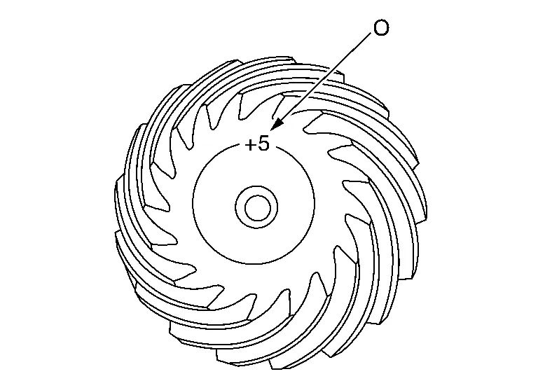 NOTE:
NOTE:
Dimension “O” indicates the difference between the optimum engagement and the standard dimensions in increments of 0.01 mm (0.0004 in) written on the gear end of drive pinion.
PINION BEARING PRELOAD
CAUTION:
When measuring preload, the rotating speed must be set to 30 rpm.
Remove ring gear shaft assembly from the transfer case. Refer to Disassembly and Assembly.
Rotate the companion flange back and forth from 2 to 3 times to check for unusual noise, binding, sticking, and so on.
Rotate the companion flange at least 20 times to check for smooth operation of the bearing.
Measure the pinion bearing preload with the preload gauge (A) [SST: ST3127S000 (J-25765-A)].

| Pinion bearing preload | : Refer to Preload Torque. |
CAUTION:
Each rotational part should rotate smoothly with the specified gear oil.
-
If outside the standard, disassemble the drive pinion assembly to check and adjust each part.
TOTAL PRELOAD
CAUTION:
When measuring preload, the rotating speed must be set to 30 rpm.
Measure pinion bearing preload.
CAUTION:
Check that the pinion bearing preload is within the standard.
Assemble the ring gear shaft assembly to the transfer case. Refer to Disassembly and Assembly.
Install transfer cover to check and adjust each part. Refer to Disassembly and Assembly.
Rotate the companion flange at least 20 times to check for smooth operation of the bearing.
Measure the total preload with the preload gauge (A) [SST: ST3127S000 (J-25765-A)].
| Total preload | : Refer to Preload Torque. |
CAUTION:
Each rotational part should rotate smoothly with the specified gear oil.
-
If outside the standard, disassemble the transfer assembly to check and adjust each part. Measure it with the transfer case oil seal and transfer cover oil seal removed when measuring total preload after disassembly. Then install transfer case oil seals and transfer cover oil seal.
BACKLASH
Install the bolt to the companion flange.
Fit a dial indicator onto the bolt .

Measure the circumference backlash of the companion flange.
| Backlash | : Refer to Backlash. |
-
If outside the standard, disassemble the transfer assembly to check and adjust each part.
TOOTH CONTACT
Remove transfer cover. Refer to Disassembly and Assembly.
Remove ring gear shaft assembly from transfer case. Refer to Disassembly and Assembly.
Apply red lead onto the ring gear.
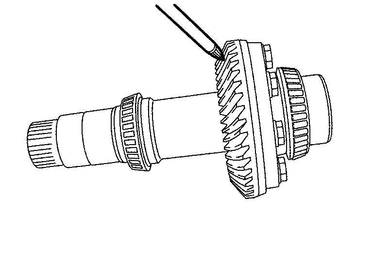
CAUTION:
Apply red lead to both faces of 3 to 4 gears at 4 locations evenly spaced on the ring gear.
Assemble the ring gear shaft assembly to the transfer case. Refer to Disassembly and Assembly.
Install transfer cover to check and adjust each part. Refer to Disassembly and Assembly.
NOTE:
At this timing, O-ring installing to transfer cover is not necessary. Install O-ring after backlash and tooth contact are checked.
Remove the plug from the transfer case.
Rotate the companion flange back and forth several times, and check the drive pinion gear to ring gear tooth contact by viewing from the plug hole.
Tooth Contact Judgment Guide
Follow the procedure below to adjust pinion height (dimension X) if tooth contact is improper. For selecting adjusting shim, refer to the latest parts information.

CAUTION:
If no adjusting shim with the calculated value is available, select the thicker and closest one.
-
Thicken the drive pinion adjusting shim to move the drive pinion closer to the ring gear in case of face contact or heel contact.

CAUTION:
Only one adjusting shim can be selected.
-
Thin the drive pinion adjusting shim to move the drive pinion farther from the ring gear in case of flank contact or toe contact.

CAUTION:
Only one adjusting shim can be selected.
COMPANION FLANGE RUNOUT
Fit a dial indicator onto the companion flange face (inner side of the propeller shaft mounting bolt holes).

Rotate the companion flange to check for runout.
| Companion flange runout | : Refer to Companion Flange Runout. |
Fit a test indicator to the inner side of the companion flange (socket diameter).
Rotate the companion flange to check for runout.
| Companion flange runout | : Refer to Companion Flange Runout. |
Follow the procedure below to adjust if runout value is outside the repair limit.Check for runout while changing the phase between companion flange and drive pinion in 90° steps. Then search for the minimum point. Replace companion flange if runout value is still outside the limit after the phase has been changed. Adjust assembly status of the pinion bearing and drive pinion, or replace pinion bearing assembly if runout is outside the standard after the companion flange is replaced.
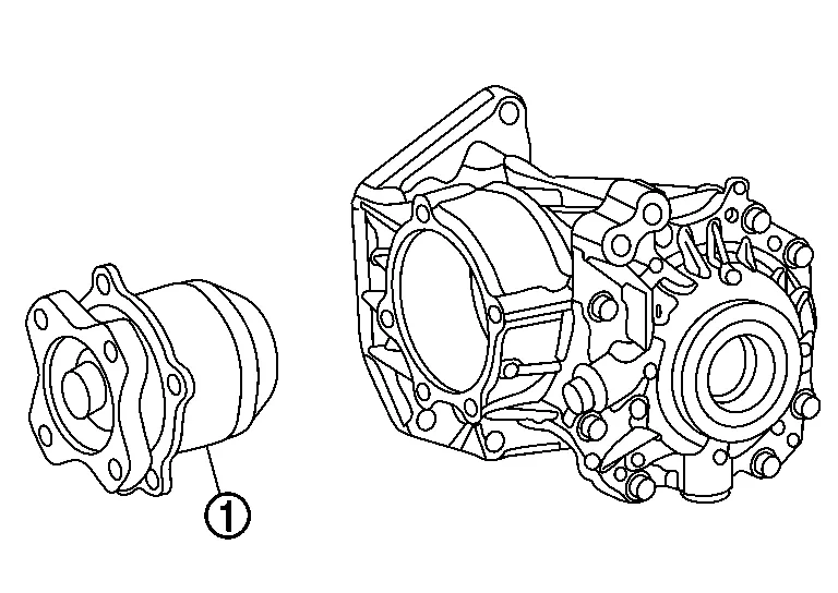
INSPECTION AFTER DISASSEMBLY
Check items below. If necessary, replace them with new ones.
Gear and Shaft
Check gear face and shaft for wear, cracks, damage, and seizure.
Replace ring gear and drive pinion as a set (hypoid gear set) if any malfunction is detected on the ring gear or drive pinion.
Bearing
Check for seizure, peeling, wear, corrosion, sticking, unusual noise, roughness in hand turning, and other damage.
Shim
Check for seizure, damage, and unusual wear.
 Ring Gear Shaft
Exploded View
Oil seal
Transfer cover
Filler plug
Gasket
Drain plug
Oil seal
O-ring
Ring gear bearing adjusting shim (transfer cover side)
Ring gear bearing (transfer cover side)
Drive shaft oil seal
Ring gear shaft
Ring gear bearing (transfer case side)
Ring gear bearing adjusting shim (transfer case side)
Ring gear
Baffle plate
Transfer case
Plug
O-ring
Oil seal
Dowel pin
Drive pinion
Drive pinion adjusting shim
O-ring
Pinion bearing assembly
Oil seal
Dust cover
Companion flange
Pinion lock nut
Oil seal lip
Comply with the assembly procedure when tightening...
 Transfer Case
Exploded View
Oil seal
Transfer cover
Filler plug
Gasket
Drain plug
Oil seal
O-ring
Ring gear bearing adjusting shim (transfer cover side)
Ring gear bearing (transfer cover side)
Drive shaft oil seal
Ring gear shaft
Ring gear bearing (transfer case side)
Ring gear bearing adjusting shim (transfer case side)
Ring gear
Baffle plate
Transfer case
Plug
O-ring
Oil seal
Dowel pin
Drive pinion
Drive pinion adjusting shim
O-ring
Pinion bearing assembly
Oil seal
Dust cover
Companion flange
Pinion lock nut
Oil seal lip
Comply with the assembly procedure when tightening...
Other information:
Nissan Murano (Z52) 2015-2024 Service Manual: B2667 Pass Sunload Sensor
DTC Description DTC DETECTION LOGICNOTE: If DTC is displayed along with DTC U1000 or U1010, first diagnose the DTC U1000 or U1010. Refer to DTC Description (U1000) or DTC Description (U1010). Sunload sensor may register a malfunction when indoors, at dusk, or at other times when light is insufficient...
Nissan Murano (Z52) 2015-2024 Service Manual: Steering Member Assembly
Exploded View 1. Heating and cooling unit assembly 2. Steering member 3. Steering member brace (LH) 4. Steering member brace (RH) A. Steering member caps Pawl Front Removal and Installation REMOVALRemove front wiper drive assembly...
Categories
- Manuals Home
- Nissan Murano Owners Manual
- Nissan Murano Service Manual
- Warning lights
- Fuel recommendation
- Turning the AEB system on/off
- New on site
- Most important about car
Front manual seat adjustment (if so equipped)
Your vehicle seats can be adjusted manually. For additional information about adjusting the seats, refer to the steps outlined in this section.
Forward and backward
