Nissan Murano: Ecu Diagnosis Information / Distance Sensor (icc Sensor)
| Monitor item | Condition | Value/Status | |
|---|---|---|---|
| VHCL SPEED SE | While driving | Value of Nissan Murano vehicle speed signal (wheel speed) | |
| YAW RATE | While driving | Nissan Murano Vehicle stopped | 0.0 |
| Nissan Murano Vehicle turning right | Positive value | ||
| Nissan Murano Vehicle turning left | Negative value | ||
| PWR SUP MONI | Ignition switch ON | Power supply voltage value of distance sensor (ICC sensor) | |
| DISTANCE | Drive the Nissan Murano vehicle and activate the ICC system. | When a vehicle ahead is detected | Displays the distance from the preceding Nissan Murano vehicle |
| When a vehicle ahead is not detected | 0.0 | ||
| RELATIVE SPD | Drive the Nissan Murano vehicle and activate the ICC system. | When a vehicle ahead is detected | Displays the relative speed |
| When a Nissan Murano vehicle ahead is not detected | 0.0 | ||
| RADAR OFFSET |
The item is displayed, but it is not used. |
— | |
| RADAR HEIGHT |
The item is displayed, but it is not used. |
— | |
| STEERING ANGLE | Ignition switch ON | When setting the steering wheel in straight-ahead position | 0.0 |
| When turning the steering wheel 90° rightward | +90 | ||
| When turning the steering wheel 90° leftward | -90 | ||
| STRG ANGLE SPEED | Ignition switch ON | At the time of turning the steering wheel | Steering wheel turning speed is displayed |
| L/R ADJUST | Ignition switch ON | At the completion of radar alignment adjustment | Horizontal correction value is displayed |
| U/D ADJUST | Ignition switch ON | At the completion of radar alignment adjustment | Vertical correction value is displayed |
| HORIZONTAL ALIGNMENT VALUE |
The item is displayed, but it is not used. |
— | |
| VERTICAL ALIGNMENT VALUE |
The item is displayed, but it is not used. |
— | |
| Nissan Murano Vehicle STATUS FOR ALIGNMENT |
The item is displayed, but it is not used. |
— | |
| ALIGNMENT STATUS |
The item is displayed, but it is not used. |
— | |
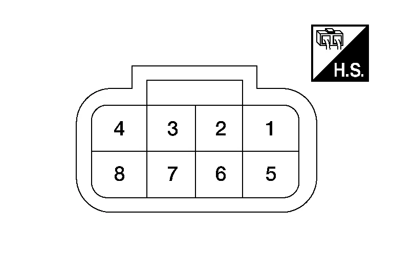
TERMINAL LAYOUT
PHYSICAL VALUES
|
Terminal No. (Wire color) | Description | Condition | Standard value |
Reference value (Approx.) | |||
|---|---|---|---|---|---|---|---|
| + | – | Signal name | Input/Output | ||||
|
1 (B) |
Ground | Ground | — | Ignition switch ON | 0 - 0.1 V | 0 V | |
|
2 (L/R) |
— | ITS communication low | — | — | — | — | |
|
3 (L) |
ITS communication high | — | — | — | — | ||
|
8 (L/W) |
Ground | Ignition power supply | Input | Ignition switch ON | 9.5 - 16 V | Battery voltage | |
Refer to Fail-safe [Distance Sensor (ICC Sensor)].
If multiple DTCs are detected simultaneously, check them one by one depending on the following DTC inspection priority chart.
| Priority | Detected items (DTC) |
|---|---|
| 1 |
|
| 2 |
|
 NOTE:
NOTE:
-
The details of time display are as per the following.
-
0: The malfunctions that are detected now
CAN communication system (U1000, U1010)
-
1 - 39: It increases like 0 → 1 → 2 ··· 38 → 39 after returning to the normal condition whenever the ignition is switched OFF → ON. It returns to 0 when a malfunction is detected again in the process.
-
If it is over 39, it is fixed to 39 until the self-diagnosis results are erased.
Other than CAN communication system (Other than U1000, U1010)
-
1 - 49: It increases like 0 → 1 → 2 ··· 48 → 49 after returning to the normal condition whenever the ignition is switched OFF → ON. It returns to 0 when a malfunction is detected again in the process.
-
If it is over 49, it is fixed to 49 until the self-diagnosis results are erased.
-
×: Applicable
| DTC | CONSULT display | ICC system warning lamp | Fail-safe function | Reference | ||
|---|---|---|---|---|---|---|
| CONSULT | Nissan Murano Vehicle-to-vehicle distance control mode | Conventional (fixed speed) cruise control mode | Automatic Emergency Braking (AEB) | |||
| C1A01-16 | POWER SUPPLY CIR | ON | × | × | × | DTC Description |
| C1A01-17 | POWER SUPPLY CIR2 | ON | × | × | × | DTC Description |
| C1A03-64 | VHCL_SPEED SE CIRC | ON | × | × | × | DTC Description |
| C1A04-97 | ABS/TCS/VDC_CIRC | ON | × | × | × | DTC Description |
| C1A12-78 | LASER BEAM OFFCNTR | ON | × | × | × | DTC Description |
| C1A16-97 | RADAR STAIN | ON | × | × | × | DTC Description |
| C1A17-44 | CONTROL UNIT | ON | × | × | × | DTC Description |
| C1A17-45 | CONTROL UNIT | ON | × | × | × | DTC Description |
| C1A17-46 | CONTROL UNIT | ON | × | × | × | DTC Description |
| C1A17-47 | CONTROL UNIT | ON | × | × | × | DTC Description |
| C1A17-48 | CONTROL UNIT | ON | × | × | × | DTC Description |
| C1A17-49 | CONTROL UNIT | ON | × | × | × | DTC Description |
| C1A18-54 | LASER AIMING INCMP | ON | × | × | × | DTC Description |
| C1A21-48 | UNIT HIGH TEMP | ON | × | × | × | DTC Description |
| C1A23-97 | UNIT LOW TEMP | ON | × | × | × | DTC Description |
| C1A39-97 | STRG SEN CIR | ON | × | × | × | DTC Description |
| C1A0C-82 | ADAS CAN CIR 1 | ON | × | × | × | DTC Description |
| C1A0C-83 | ADAS CAN CIR 1 | ON | × | × | × | DTC Description |
| C10B7-64 | YAW RATE SENSOR | ON | × | × | × | DTC Description |
| U0428-83 | STRG SEN CAN CIR2 | ON | × | × | × | DTC Description |
| U0121-83 | VDC CAN CIR2 | ON | × | × | × | DTC Description |
| U0126-82 | STRG SEN CAN CIR1 | ON | × | × | × | DTC Description |
| U1000-01 | CAN COMM CIRCUIT | ON | × | × | × | DTC Description |
| U1010-49 | CONTROL UNIT (CAN) | ON | × | × | × | DTC Description |


Other information:
Nissan Murano (Z52) 2015-2024 Owners Manual: Jump starting
To start your engine with a booster battery, the instructions and precautions below must be followed. WARNING If done incorrectly, jump starting can lead to a battery explosion, resulting in severe injury or death. It could also damage your vehicle...
Nissan Murano (Z52) 2015-2024 Service Manual: Power Steering Oil Pump
Exploded View 1. Power steering reservoir cap 2. Power steering oil pump 3. Low-pressure piping 4. High-pressure piping Front Removal and Installation WARNING: Power steering pump outer shell will be hot while running and after driving...
Categories
- Manuals Home
- Nissan Murano Owners Manual
- Nissan Murano Service Manual
- Power Steering Fluid (PSF)
- Vehicle Dynamic Control (VDC) OFF switch
- GAS STATION INFORMATION
- New on site
- Most important about car
Vehicle security system

Your vehicle has two types of security systems:
Vehicle security system NISSAN Vehicle Immobilizer SystemThe vehicle security system provides visual and audible alarm signals if someone opens the doors, liftgate or the hood when the system is armed. It is not, however, a motion detection type system that activates when a vehicle is moved or when a vibration occurs.