Nissan Murano: System Description / Diagnosis System (tcm). Diagnosis Description
 NOTE:
NOTE:
“Start the engine and turn OFF the ignition switch after warm-up.” This is defined as 1 trip.
1 TRIP DETECTION DIAGNOSIS
When initial malfunction is detected, TCM memorizes DTC. In these diagnoses, some illuminate MIL and some do not. Refer to DTC Index.
2 TRIP DETECTION DIAGNOSIS
When initial malfunction is detected, TCM memorizes DTC of the 1st trip. MIL does not light at this stage. <1 trip>
If the same malfunction is detected again in next driving, TCM memorizes DTC. When DTC is memorized, MIL lights. <2 trip>
“Trip” of the “2 trip detection diagnosis” indicates the driving mode that executes self-diagnosis during driving.
×: Check possible —: Check not possible
| Item | DTC at the 1st trip | DTC | MIL | |||
|---|---|---|---|---|---|---|
| Display at the 1st trip | Display at the 2nd trip | Display at the 1st trip | Display at the 2nd trip | Illumination at the 1st trip | Illumination at the 2nd trip | |
|
1 trip detection diagnosis (Refer to DTC Index) |
— | — | × | — | × | — |
|
2 trip detection diagnosis (Refer to DTC Index) |
× | — | — | × | — | × |
2 TRIP DETECTION DIAGNOSIS THAT ILLUMINATES MIL
-
The DTC number of the 1st trip is the same as the DTC number.
-
When a malfunction is detected at the 1st trip, TCM memorizes DTC of the 1st trip. MIL does not light at this stage. If the same malfunction is not detected at the 2nd trip (conforming to necessary driving conditions), DTC at the 1st trip is erased from TCM. If the same malfunction is detected at the 2nd trip, TCM memorizes DTC and MIL lights at the same time.
-
The DTC of the 1st trip is specified in Service $07 of SAE J1979/ISO 15031-5. Since detection of DTC at the 1st trip does not illuminate MIL, warning for a problem is not given to a driver.
-
For procedure to delete DTC and 1st trip DTC from TCM, refer to CONSULT Function.
-
If DTC of the 1st trip is detected, it is necessary to check the cause according to the “Diagnosis flow”. Refer to Work Flow.
-
TCM not only detects DTC, but also sends the MIL signal to ECM through CAN communication. ECM sends the MIL signal to the combination meter through CAN communication according to the signal, and illuminates MIL.
-
For malfunction indicator lamp (MIL) description, refer to Malfunction Indicator Lamp (MIL).
Permanent DTC is defined in SAE J1979/ISO 15031-5 Service $0A.
TCM stores a DTC issuing a command of turning on MIL as a permanent DTC and keeps storing the DTC as a permanent DTC until TCM judges that there is no presence of malfunction.
Permanent DTCs cannot be erased by using the erase function of CONSULT or Generic Scan Tool (GST) and by disconnecting the battery to shut off power to TCM. This prevents a Nissan Murano vehicle from passing the in-use inspection without repairing a malfunctioning part.
When not passing the in-use inspection due to more than one permanent DTC, permanent DTCs should be erased, referring to this manual.
NOTE:
-
Permanent DTCs do not apply for regions that permanent DTCs are not regulated by law.
PERMANENT DTC SET TIMING
The setting timing of permanent DTC is stored in TCM with the lighting of MIL when a DTC is confirmed.
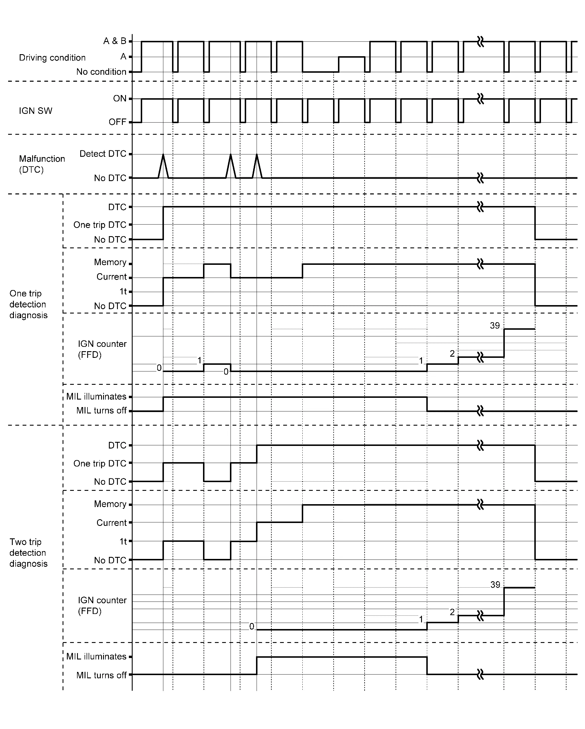
RELATION BETWEEN DTC AT 1ST TRIP/DTC/MIL AND DRIVING CONDITIONS (FOR 2 TRIP DETECTION DIAGNOSIS THAT ILLUMINATES MIL)
-
When initial malfunction is detected, TCM memorizes DTC of the 1st trip. MIL does not light at this stage.
-
If the same malfunction is detected at the 2nd trip, TCM memorizes DTC and MIL lights at the same time.
-
Then, MIL goes off after driving the Nissan Murano vehicle for 3 trips under “Driving condition B” without malfunction.
-
DTC is displayed until 40 trips of “Driving condition A” are satisfied with no malfunction on “Driving condition A” after MIL lighting off. DTC is erased when 40 trips are satisfied.
-
When the self-diagnosis result is acceptable at the 2nd trip (conforming to driving condition B), DTC of the 1st trip is erased.
COUNTER SYSTEM LIST
| Item | Driving condition | Trip |
|---|---|---|
| MIL (OFF) | B | 3 |
| DTC (clear) | A | 40 |
| DTC at 1st trip (clear) | B | 1 |
DRIVING CONDITION
Driving condition A
Driving condition A is the driving condition that provides warm-up.
In specific, count-up is performed when all of the following conditions are satisfied.
-
Engine speed is 400 rpm or more.
-
After start of the engine, the water temperature increased by 20°C (36°F) or more.
-
Water temperature was 70°C (158°F) or more.
-
The ignition switch was changed from ON to OFF.
NOTE:
-
If the same malfunction is detected regardless of the driving condition, reset the A counter.
-
When the above is satisfied without detecting the same malfunction after turning of MIL, count up the A counter.
-
When MIL goes off due to the malfunction and the A counter reaches 40, the DTC is erased.
Driving condition B
Driving condition B is different by each DTC.
In specific, count-up is performed when the following conditions are satisfied.
| DTC | Driving condition | ||||||||||||
|---|---|---|---|---|---|---|---|---|---|---|---|---|---|
| U0073, U0100, U0122, P0718, P0794, P2768 | Start the engine and let it idle for least 2 seconds. | ||||||||||||
| P062F, P0740, P0743, P0778, P0779, P0863, P0890, P0962, P0963, P0966, P0967 | Start the engine and let it idle for least 1 second. | ||||||||||||
| P0711 |
|
||||||||||||
| P0712 | Start the engine and let it idle for least 5 seconds. | ||||||||||||
| P0705 |
|
||||||||||||
| P0706 |
|
||||||||||||
| P0713 |
Drive the Nissan Murano vehicle for 5 seconds or more under the following conditions.
|
||||||||||||
| P0715, P0716, P0717, P0791, P0792, P0793 |
Drive the Nissan Murano vehicle for 5 seconds or more under the following conditions.
|
||||||||||||
| P0741 |
Drive the vehicle for 10 seconds or more under the following conditions.
|
||||||||||||
| P0742 |
|
||||||||||||
| P0746 |
Drive the Nissan Murano vehicle for 5 seconds or more under the following conditions.
|
||||||||||||
| P0776 |
Drive the vehicle for 10 seconds or more under the following conditions.
|
||||||||||||
| P0841 |
Drive the vehicle for 5 seconds or more under the following conditions.
|
||||||||||||
| P0847, P0848, P084C, P084D |
Start the engine and wait for at least 10 seconds. CAUTION: When the ambient temperature is less than −20°C (−4°F) and the engine is cold, warm up the engine for approximately 5 minutes. |
||||||||||||
| P0965 |
Drive the Nissan Murano vehicle for 10 seconds or more under the following conditions.
|
||||||||||||
| P1588 |
Drive the Nissan Murano vehicle for 10 seconds or more under the following conditions.
|
||||||||||||
| P159C |
Drive the Nissan Murano vehicle for 10 seconds or more under the following conditions.
|
||||||||||||
| P159D |
Drive the Nissan Murano vehicle for 10 seconds or more under the following conditions.
|
||||||||||||
| P2758 | Drive the Nissan Murano vehicle at coasting. | ||||||||||||
| P2765, P2766, P2767 |
Drive the vehicle for 5 seconds or more under the following conditions.
|
||||||||||||
| P2813 |
|
||||||||||||
| P2814, P2815 |
|
NOTE:
-
If the same malfunction is detected regardless of the driving condition, reset the B counter.
-
When the above is satisfied without detecting the same malfunction, count up the B counter.
-
When the B counter reaches 3 without malfunction, MIL goes off.
-
When the B counter is counted once without detecting the same malfunction after TCM memorizes DTC of the 1st trip, DTC of the 1st trip is erased.
TIME CHART
CAUTION:
After disconnecting the CONSULT vehicle interface (VI) from the data link connector, the ignition must be cycled OFF → ON (for at least 5 seconds) → OFF. If this step is not performed, the BCM may not go to “sleep mode”, potentially causing a discharged battery and a no-start condition.
APPLICABLE ITEM
| Mode | Function |
|---|---|
| Work Support | The settings for ECU functions can be changed. |
| Self Diagnostic Results | The ECU self diagnostic results are displayed. |
| Data Monitor | The ECU input/output data is displayed in real time. |
| CAN Diagnosis Support Monitor | The result of transmit/receive diagnosis of CAN communication is displayed. |
| Active Test | The ECU activates outputs to test components. |
| ECU Identification | The ECU part number is displayed. |
| CALIB DATA | The calibration data status of TCM can be checked. |
SELF DIAGNOSTIC RESULTS
Refer to DTC Index.
DTC at 1st trip and method to read DTC
-
DTC (P0705, P0711, P0720, etc.) is specified by SAE J2012/ISO 15031-6.
-
DTC and DTC at 1st trip are displayed on “Self Diagnostic results” of CONSULT.
When DTC is currently detected, “CRNT” is displayed. If “PAST” is displayed, it shows a malfunction occurred in the past. The trip number of drive without malfunction of concerned DTC can be confirmed with “IGN counter” inside “FFD”.
-
When the DTC at the 1st trip is detected, “1t” is displayed.
DTC deletion method
NOTE:
If the ignition switch is left ON after repair, turn OFF the ignition switch and wait for 10 seconds or more. Then, turn the ignition ON again. (Engine stop)
-
Touch “TRANSMISSION” of CONSULT.
-
Touch “Self Diagnostic Result”.
-
Touch “Erase”. (DTC memorized in TCM is erased.)
IGN counter
The ignition counter is displayed in “FFD” and the number of times of satisfied “Driving condition A” is displayed after normal recovery of DTC. Refer to Counter System.
-
If malfunction (DTC) is currently detected, “0” is displayed.
-
After normal recovery, every time “Driving condition A” is satisfied, the display value increases from 1 → 2 → 3...38 → 39.
-
When MIL turns OFF due to the malfunction and the counter reaches 40, the DTC is erased.
NOTE:
The counter display of “40” cannot be checked.
DATA MONITOR
NOTE:
The following table includes information (items) inapplicable to this Nissan Murano vehicle. For information (items) applicable to this vehicle, refer to CONSULT display items.
| Monitored item | (Unit) | Remarks |
|---|---|---|
| VSP SENSOR | (km/h or mph) | Displays the Nissan Murano vehicle speed calculated from the CVT output shaft speed. |
| ESTM VSP SIG | (km/h or mph) |
|
| INPUT SPEED SENSOR | (rpm) | Displays the input speed calculated from the pulse signal of the input speed sensor. |
| PRI SPEED SEN | (rpm) | Displays the primary pulley speed calculated from the pulse signal of the primary speed sensor. |
| SEC REV SENSOR | (rpm) | Displays the secondary pulley speed calculated from the pulse signal of the output speed sensor. |
| ENG SPEED SIG | (rpm) | Displays the engine speed received through CAN communication. |
| SEC PRESSURE SEN | (V) | Displays the signal voltage of the secondary pressure sensor. |
| PRI PRESSURE SEN | (V) | Displays the signal voltage of the primary pressure sensor. |
| ATF TEMP SEN | (V) | Displays the signal voltage of the CVT fluid temperature sensor. |
| G SENSOR | (G) | Displays the signal voltage of the G sensor. |
| VIGN SEN | (V) | Displays the battery voltage applied to TCM. |
| PVING VOLT | (V) | Displays the backup voltage of TCM. |
| Nissan Murano Vehicle SPEED | (km/h or mph) | Displays the Nissan Murano vehicle speed recognized by TCM. |
| INPUT REV | (rpm) | Displays the input shaft speed of CVT recognized by TCM. |
| PRI SPEED | (rpm) | Displays the primary pulley speed recognized by TCM. |
| SEC SPEED | (rpm) | Displays the secondary pulley speed recognized by TCM. |
| ENG SPEED | (rpm) | Displays the engine speed recognized by TCM. |
| SLIP REV | (rpm) | Displays the speed difference between the input shaft speed of CVT and the engine speed. |
| PULLEY GEAR RATIO | Displays the pulley gear ratio calculated from primary pulley speed/secondary pulley speed. | |
| G SPEED | (G) | Displays the acceleration and deceleration speed of the Nissan Murano vehicle calculated from vehicle speed change. |
| ACCEL POSI SEN 1 | (deg) | Displays the estimated throttle position received through CAN communication. |
| VENG TRQ | (Nm) | Display the engine torque recognized by TCM. |
| PRI TRQ | (Nm) | Display the input shaft torque of CVT. |
| TRQ RTO | Display the torque ratio of torque converter. | |
| SEC PRESSURE | (MPa) | Displays the secondary pressure calculated from the signal voltage of the secondary pressure sensor. |
| PRI PRESSURE | (MPa) | Displays the primary pressure calculated from the signal voltage of the primary pressure sensor. |
| FLUID TEMP | (°C or °F) | Displays the CVT fluid temperature calculated from the signal voltage of the CVT fluid temperature sensor. |
| DSR REV | (rpm) | Displays the target primary pulley speed calculated from processing of gear shift control. |
| TGT PLLY GR RATIO | Displays the target gear ratio of the pulley from processing of gear shift control. | |
| LU PRS | (MPa) | Displays the target oil pressure of the torque converter clutch solenoid valve calculated from oil pressure processing of gear shift control. |
| LINE PRS | (MPa) | Displays the target oil pressure of the line pressure solenoid valve calculated from oil pressure processing of gear shift control. |
| TRGT PRI PRESSURE | (MPa) | Displays the target oil pressure of the primary pressure solenoid valve calculated from oil pressure processing of gear shift control. |
| TRGT SELECT PRESSURE | (MPa) | Displays the target oil pressure of the select solenoid valve calculated from oil pressure processing of gear shift control. |
| TRGT SEC PRESSURE | (MPa) | Displays the target oil pressure of the secondary pressure solenoid valve calculated from oil pressure processing of gear shift control. |
| ISOLT1 | (A) | Displays the command current from TCM to the torque converter clutch solenoid valve. |
| ISOLT2 | (A) | Displays the command current from TCM to the line pressure solenoid valve. |
| PRI SOLENOID | (A) | Displays the command current from TCM to the primary pressure solenoid valve. |
| SEC SOLENOID CURRENT | (A) | Displays the command current from TCM to the secondary pressure solenoid valve. |
| SELECT SOLENOID CURRENT | (A) | Displays the command current from TCM to the select solenoid valve. |
| SOLMON1 | (A) | Monitors the command current from TCM to the torque converter clutch solenoid valve and displays the monitored value. |
| SOLMON2 | (A) | Monitors the command current from TCM to the line pressure solenoid valve and displays the monitored value. |
| PRI SOL MON | (A) | Monitors the command current from TCM to the primary pressure solenoid valve and displays the monitored value. |
| SEC SOL MON CURRENT | (A) | Monitors the command current from TCM to the secondary pressure solenoid valve and displays the monitored value. |
| SELECT SOL MON CURRENT | (A) | Monitors the command current from TCM to the select solenoid valve and displays the monitored value. |
| D POSITION SW | (On/Off) | Displays the operation status of the transmission range switch (D position). |
| N POSITION SW | (On/Off) | Displays the operation status of the transmission range switch (N position). |
| R POSITION SW | (On/Off) | Displays the operation status of the transmission range switch (R position). |
| P POSITION SW | (On/Off) | Displays the operation status of the transmission range switch (P position). |
| L POSITION SW* | (On/Off) | Displays the operation status of the transmission range switch (L position). |
| DS RANGE SW* | (On/Off) | Displays the operation status of the transmission range switch (DS position). |
| BRAKESW | (On/Off) | Displays the reception status of the stop lamp switch signal received through CAN communication. |
| IDLE SW | (On/Off) | Displays the reception status of the closed throttle position signal received through CAN communication. |
| SPORT MODE SW* | (On/Off) | Displays the reception status of the overdrive control switch signal received through CAN communication. |
| ECO MODE SW* | (On/Off) | Displays the reception status of the ECO mode switch signal received through CAN communication. |
| STRDWNSW* | (On/Off) | Displays the operation status of the paddle shifter (down switch). |
| STRUPSW* | (On/Off) | Displays the operation status of the paddle shifter (up switch). |
| DOWNLVR | (On/Off) | Displays the operation status of the selector lever (down switch). |
| UPLVR | (On/Off) | Displays the operation status of the selector lever (up switch). |
| NONMMODE | (On/Off) | Displays if the selector lever position is not at the manual shift gate. |
| MMODE | (On/Off) | Displays if the selector lever position is at the manual shift gate. |
| TOW MODE SW* | (On/Off) | Displays the reception status of the TOW mode switch signal received through CAN communication. |
| SHIFT IND SIGNAL | Displays the transaxle value of shift position signal transmitted via CAN communication. | |
| CVT LAMP* | (On/Off) | Displays the transaxle status of the CVT warning lamp signal transmitted through CAN communication. |
| SPORT MODE IND* | (On/Off) | Displays the transaxle status of the O/D OFF indicator lamp signal transmitted through CAN communication. |
| MANU MODE SIGNAL | (On/Off) | Displays the transaxle status of the manual mode signal transmitted through CAN communication. |
| DS RANGE SIGNAL* | (On/Off) | Displays the shift position signal status from transmission range switch (DS position). |
| ECO MODE SIGNAL* | (On/Off) | Displays the transaxle status of the ECO mode signal transmitted through CAN communication. |
| VDC ON | (On/Off) | Displays the reception status of the VDC operation signal received through CAN communication. |
| TCS ON | (On/Off) | Displays the reception status of the TCS operation signal received through CAN communication. |
| ABS FAIL SIGNAL | (On/Off) | Displays the reception status of the ABS malfunction signal received through CAN communication. |
| ABS ON | (On/Off) | Displays the reception status of the ABS operation signal received through CAN communication. |
| RANGE | Displays the gear position recognized by TCM. | |
| M GEAR POS | Display the target gear of manual mode | |
| G SEN SLOPE | (%) | Displays the gradient angle calculated from the G sensor signal voltage. |
| G SEN CALIBRATION | (YET/DONE) | Displays the status of “G SENSOR CALIBRATION” in “Work Support”. |
| N IDLE STATUS* | (On/Off) | Displays idle neutral status. |
| ENGBRKLVL | (On/Off) | Displays the setting of “ENGINE BRAKE ADJ” in “Work Support”. |
| DRIVE MODE STATS | Displays the drive mode status recognized by TCM. | |
| SNOW MODE | (On/Off) | Displays whether it is the SNOW mode. |
| ECO MODE | (On/Off) | Displays whether it is the ECO mode. |
| NORMAL MODE | (On/Off) | Displays whether it is the NORMAL mode. |
| SPORT MODE | (On/Off) | Displays whether it is the SPORT mode. |
| AIR BLDING STATE* | (INCOMP/COMP) | Displays the status of “ELECTRIC O.P. AIR BLEEDING” in “Work Support”. |
| ELECTRIC OP DUTY* | (%) | Displays the command signal value (duty) of the electric oil pump transmitted from TCM. |
| E-OP DUTY MON* | (%) | Monitors the status signal value (duty) transmitted from the electric oil pump and displays the monitored value. |
| ELECTRIC OP RELAY* | (On/Off) | Displays the command status from TCM to the electric oil pump relay. |
| E-OP RELAY MON* | (On/Off) | Monitors the command status from TCM to the oil pump relay and displays the monitored value. |
| CVT-B |
|
|
| CVT-A | (On/Off) |
|
| AXLE TYPE | Displays the axle type of the Nissan Murano vehicle. | |
| T/M warning indicator DTC* | The first DTC only turns on the A/T warning indicator is displayed | |
| T/M warning indicator milege* | When the A/T warning indicator is turned on at first time, the total mileage is displayed. |
*: Not applicable but displayed.
WORK SUPPORT
| Item name | Description |
|---|---|
| CONFORM CVTF DETERIORTN | Checks the degradation level of the CVT fluid under severe conditions. |
| G SENSOR CALIBRATION | Compensates the G sensor. |
| ERASE LEARNING VALUE* | Erases learning value memorized by TCM. |
| ENGINE BRAKE ADJ. | Although there is no malfunction on the transaxle and the CVT system, if a customer make a complaint like “I do not feel comfortable with automatic operation of the engine brake on downhill”, the engine brake may be cancelled with “engine brake adjustment”. |
| FWD CLUTCH POINT LEARNING | Allows TCM to learn clutch engagement point. |
| WRITE IP CHARA - REPLACEMENT AT/CVT | Writes IP characteristics when transaxle assembly is replaced. |
| READ IP CHARA - REPLACEMENT TCM | Reads IP characteristics when TCM is replaced. |
| WRITE IP CHARA - REPLACEMENT TCM | Writes IP characteristics when TCM is replaced. |
| CVT INSPECTION* | ― |
*: This item is not used.
Engine brake adjustment
| ENGINE BRAKE LEVEL | |
| ON | : Turn ON the engine brake control. |
| OFF | : Turn OFF the engine brake control. |
Check the degradation level of the CVT fluid.
| CVTF degradation level data | |
| 210,000 or more | : Replacement of the CVT fluid is required. |
| Less than 210,000 | : Replacement of the CVT fluid is not required. |
ACTIVE TEST
| Item name | Description |
|---|---|
| CVT OIL COOLER FAN CIRCUIT* | Checks the operation of CVT oil cooler fan relay. |
*: This item is not used.
 On Board Diagnostic (obd) System
Description
This is an on board diagnosis system which records diagnosis information related to the exhaust gases. It detects malfunctions related to sensors and actuators...
 Ecu Diagnosis Information. Tcm
Reference Value
CONSULT DATA MONITOR STANDARD VALUE
In CONSULT, electric shift timing or lock-up timing, i.e. operation timing of each solenoid valve, is displayed...
Other information:
Nissan Murano (Z52) 2015-2024 Service Manual: Diagnosis and Repair Workflow
Work Flow OVERALL SEQUENCE Reference 1: Refer to CONSULT Function. Reference 2: Refer to DTC Index. Reference 3: Refer to Symptom Table. DETAILED FLOWINTERVIEW AND SYMPTOM CONFIRMATION Check the malfunction symptoms by performing the following items: Interview the customer to obtain the malfunction information (conditions and environment when the malfunction occurred)...
Nissan Murano (Z52) 2015-2024 Service Manual: B132a External Usb
DTC Description DTC DETECTION LOGIC DTC No. CONSULT screen terms (Trouble diagnosis content) DTC detection condition B132A–13 External USB (USB) [OPEN] Diagnosis condition When ignition switch is ON. Signal (terminal) — Threshold – Diagnosis delay time 30 seconds or more B132A–01 [–] Diagnosis condition When ignition switch is ON...
Categories
- Manuals Home
- Nissan Murano Owners Manual
- Nissan Murano Service Manual
- Shift lock release
- Checking engine oil level
- System malfunction
- New on site
- Most important about car
LATCH (Lower Anchors and Tethers for CHildren) system

LATCH system lower anchor locations - bench seat
Your vehicle is equipped with special anchor points that are used with LATCH system compatible child restraints. This system may also be referred to as the ISOFIX or ISOFIX compatible system. With this system, you do not have to use a vehicle seat belt to secure the child restraint unless the combined weight of the child and child restraint exceeds 65 lbs. (29.5 kg). If the combined weight of the child and child restraint is greater than 65 lbs. (29.5 kg), use the vehicle’s seat belt (not the lower anchors) to install the child restraint. Be sure to follow the child restraint manufacturer’s instructions for installation.