Nissan Murano: Srs Air Bag Control System :: System Description / Diagnosis System (air Bag)
CAUTION:
-
Do not use electrical test equipment on any circuit related to the SRS unless instructed to do so in this Service Manual. SRS wiring harnesses can be identified by yellow and/or orange harness connectors.
-
Do not attempt to repair, splice or modify SRS wiring harnesses. If a harness is damaged, replace it with a new one.
-
Keep ground connections clean.
HOW TO PERFORM TROUBLE DIAGNOSES FOR QUICK AND ACCURATE REPAIR
-
Obtain information about the symptom.
-
WHAT - vehicle model
-
WHEN - date, frequencies
-
WHERE - road conditions
-
HOW - operating conditions, symptoms, passengers
-
-
Perform Preliminary Check.
-
Battery
-
Fuses
-
Harness connections
-
DIAGNOSIS METHODS
SRS “Self Diagnostic Result” can be read by using the AIR BAG warning lamp or CONSULT.
The User Mode is for the customer (driver). This mode warns the driver of a system malfunction through the AIR BAG warning lamp.
The Diagnosis Mode is for the technician. This mode helps the technician locate the malfunctioning circuit or part.
| Diagnosis tool | User Mode | Diagnosis Mode | Display type |
|---|---|---|---|
| AIR BAG warning lamp | X | X | ON/OFF |
| CONSULT | — | X | Monitoring |
USER MODE
-
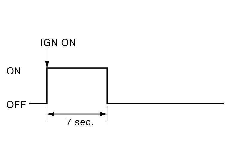
Place the ignition switch from OFF to ON and check that the air bag warning lamp blinks.
-
Compare the blinking pattern with the examples in the table.
| Warning lamp | SRS condition | Reference item |
|---|---|---|
|
|
|
— |
|
|
|
Refer to For Frontal Collision or For Side and Rollover Collision. |
|
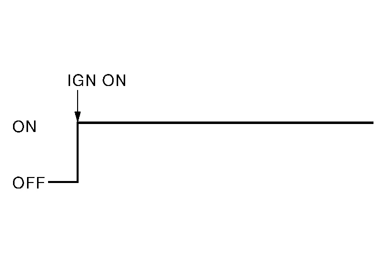
Refer to Air Bag Warning Lamp Does Not Turn Off. | |
|
|
|
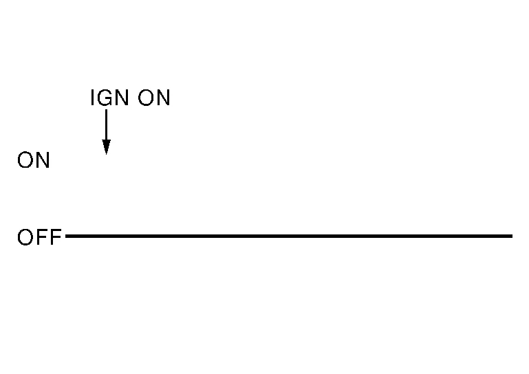
Refer to Air Bag Warning Lamp Does Not Turn On. |
 CONSULT
DTC is displayed on “Self Diagnostic Result”.
 NOTE:
NOTE:
If a malfunction is not detected on “Self Diagnostic Result [CURRENT]”, but a malfunction is detected during SRS Operation Check, the following cases may exist:
-
“Self Diagnostic Result [PAST]” memory might not be erased. Refer to SRS Final Check.
-
SRS system malfunctions intermittently. Refer to Inspection Procedure.
SRS HISTORY CHECK
-
Check repair history of the SRS. If no repairs have been made, perform SRS Operation Check. If repairs have been made, GO TO step 2.
-
Erase “Self Diagnostic Result [PAST]” after repair. Refer to SRS Final Check.
DIAGNOSIS MODE
CONSULT
-
Confirm that zero point reset of OCS is complete.
-
If no DTCs are detected on “Self Diagnostic Result [CURRENT]”, repair of SRS is completed. Go to step 3.
If any DTCs are detected on “Self Diagnostic Result [CURRENT]”, the malfunction has not been repaired completely or another malfunction is being detected. Perform SRS Operation Check again. Refer to SRS Operation Check.
-
Select “ERASE”.
NOTE:
Selecting “ERASE” will clear the SRS memory of the malfunction (“Self Diagnostic Result [PAST]”). If “Self Diagnostic Result [PAST]” is not erased, User Mode may show the previous system malfunction even if the malfunction has been repaired completely.
-
Check that no malfunction is detected in “Self Diagnostic Result [PAST]”.
-
Exit Diagnosis Mode and disconnect the CONSULT.
-
Perform SRS Operation Check. Refer to SRS Operation Check.
CAUTION:
After disconnecting the CONSULT vehicle interface (VI) from the data link connector, the ignition must be cycled OFF → ON (for at least 5 seconds) → OFF. If this step is not performed, the BCM may not go to ”sleep mode”, potentially causing a discharged battery and no-start condition.
APPLICATION ITEMS
CONSULT can display each diagnostic item using the diagnostic test modes shown following:
| Diagnostic Test Mode | Diagnostic Item | Description |
|---|---|---|
| Self Diagnostic Result | SELF DIAGNOSTIC RESULT [CURRENT] | A current “Self Diagnostic Result” (also indicated by the number of warning lamp flashes in the Diagnosis mode) is displayed on the CONSULT screen in real time. This refers to a malfunctioning part requiring repairs. |
| Data Monitor | DATA MONITOR | Displays air bag diagnosis sensor unit input/output data in real time. |
| ECU Identification | ECU DISCRIMINATED NO. | Air bag diagnosis sensor unit ECU discriminated number (identification number) or part number is displayed. Air bag diagnosis sensor unit has individual ECU discriminated number (identification number) or part number based on model and equipment. |
| TROUBLE DIAG RECORD | TROUBLE DIAG RECORD [PAST] | With “TROUBLE DIAG RECORD”, diagnosis results previously erased by a reset operation can be displayed on the CONSULT screen. |
| Configuration | CONFIGURATION |
|
CONSULT can display each diagnostic item using the diagnostic test modes shown following:
NOTE:
The following table includes information (items) inapplicable to this Nissan Murano vehicle. For information (items) applicable to this vehicle, refer to CONSULT display items.
| Diagnostic Test Mode | Diagnostic Item | Description |
|---|---|---|
| Work support | Zero point reset function | Perform zero point reset. Refer to Special Repair Requirement. |
| Data Monitor |
Buckle Switch Status (Comm) [Not Moni/Moni(wir)/Frm ACU] |
Displays the status of the seat belt buckle switch (passenger side) signal.
|
|
Buckle Switch Spec [Not Moni/Nor Op/Nor Cl/ Frm ACU] |
Displays the spec of the seat belt buckle switch (passenger side).
|
|
|
Buckle Switch Status [Not Moni/Unfasten/ Fasten/Reload] |
The switch status input from seat belt buckle switch (passenger side).
|
 Seat Belt Warning Lamp System
System Description
SYSTEM DIAGRAMSystem DescriptionThe seat belt warning lamp (1) will remind the driver if the driver or front passenger seat belt should be buckled...

Other information:
Nissan Murano (Z52) 2015-2024 Service Manual: U1000 Can Comm Circuit
DTC Description DESCRIPTIONCAN (Controller Area Network) is a serial communication system for real-time application. It is an on-Nissan Murano vehicle multiplex communication system with high data communication speed and excellent error detection ability...
Nissan Murano (Z52) 2015-2024 Service Manual: Wheel Hub
On-vehicle Service Check axle and suspension parts for excessive play, wear or damage. Move the wheel as shown to check for excessive play. Inspection Check wheel hub bearing axial end play. Axial end play : Refer to Wheel Bearing. Check that wheel hub bearings operate smoothly...
Categories
- Manuals Home
- Nissan Murano Owners Manual
- Nissan Murano Service Manual
- Passenger compartment
- Warning lights
- System malfunction
- New on site
- Most important about car
Driver and passenger supplemental knee air bag

Driver’s side
The knee air bag is located in the knee bolster, on the driver’s and passenger’s side. All of the information, cautions and warnings in this manual apply and must be followed. The knee air bag is designed to inflate in higher severity frontal collisions, although it may inflate if the forces in another type of collision are similar to those of a higher severity frontal impact. It may not inflate in certain collisions.

Passenger’s side