Nissan Murano: Engine Mechanical :: Removal and Installation / Cylinder Head
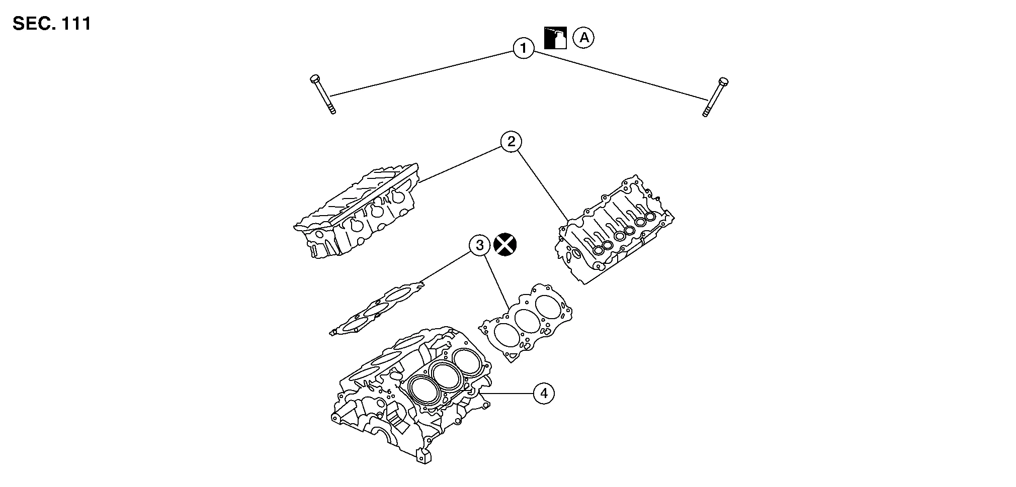
| 1. | Cylinder head bolt | 2. | Cylinder head | 3. | Cylinder head gasket |
| 4. | Engine block | A. | Refer to Removal and Installation. |
REMOVAL
Remove the engine from the vehicle. Refer to Removal and Installation (FWD) or Removal and Installation (AWD).
Remove the rear timing chain case. Refer to Removal and Installation.
Remove the intake manifold. Refer to Removal and Installation.
Remove the exhaust manifold and three way catalyst (bank 1/bank 2). Refer to Exploded View.
Remove the intake and exhaust camshafts. Refer to Removal and Installation.
Remove the water outlet housing. Refer to Exploded View.
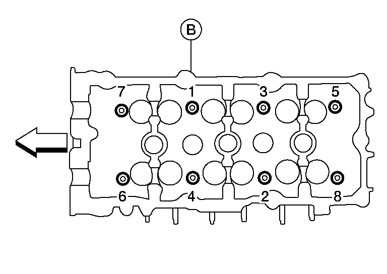
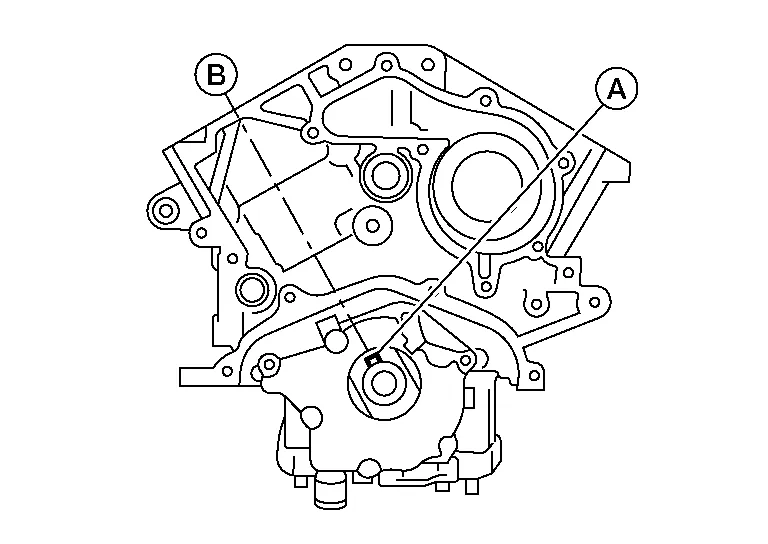
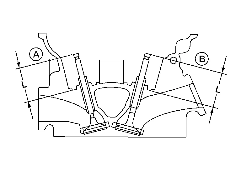
Remove the bolts from bank 1 cylinder head (A) and bank 2 cylinder head (B).
-
The bolts should be loosened gradually in three stages.
-
Loosen the bolts in the reverse tightening sequence as shown.
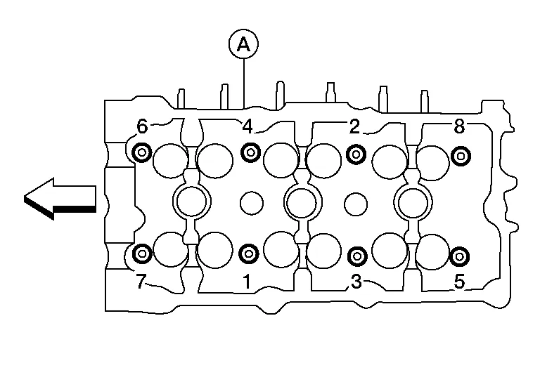
| :Engine front |
Remove cylinder head (A) and cylinder head gasket.
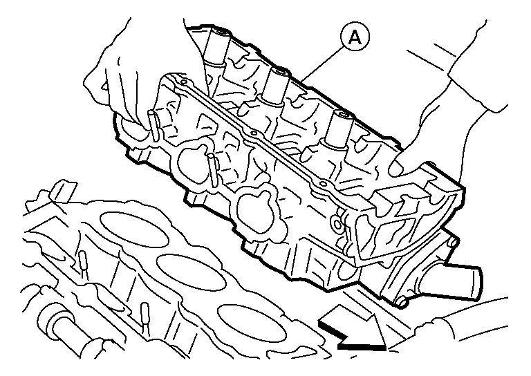
CAUTION:
Do not reuse cylinder head gaskets.
| :Engine front |
INSTALLATION
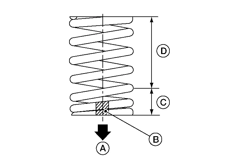
Turn the crankshaft until No. 1 piston is set at TDC on the compression stroke.
-
The crankshaft key (A) should line up with the bank 1 cylinder head center line (B) as shown.
Install new cylinder head gaskets.
CAUTION:
Do not reuse cylinder head gaskets.
Inspect the cylinder head bolts (B) before installing the cylinder heads.
CAUTION:
-
Cylinder head bolts (B) are tightened by degree rotation tightening method. Observing measuring points (A), whenever the size difference between d1 and d2 exceeds the limit, replace the bolts with new ones.
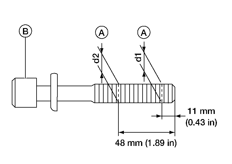
| Limit (d1 - d2) | : 0.11 mm (0.0043 in) |
-
Lubricate threads and seat surfaces of the bolts with new engine oil.
Install the bank 1 cylinder head (A) and bank 2 cylinder head (B) on the cylinder block. Tighten the cylinder head bolts in the five steps in the numerical order as shown using Tool.
CAUTION:
Do not rotate crankshaft and camshaft separately or valves will strike piston heads.
| Tool Number | : KV10112100 (BT-8653-A) |
-
Tightening procedure:
| Cylinder head bolts | |
| Step 1 | : 98.1 N·m (10 kg-m, 72 ft-lb) in order |
| Step 2 | : Loosen bolts in the reverse order of tightening. |
| Step 3 | : 39.2 N·m (4.0 kg-m, 29 ft-lb) in order |
| Step 4 | : 103° degrees rotation in order |
| Step 5 | : 103° degrees rotation in order |
| :Engine front |
Installation of the remaining components is in the reverse order of removal.
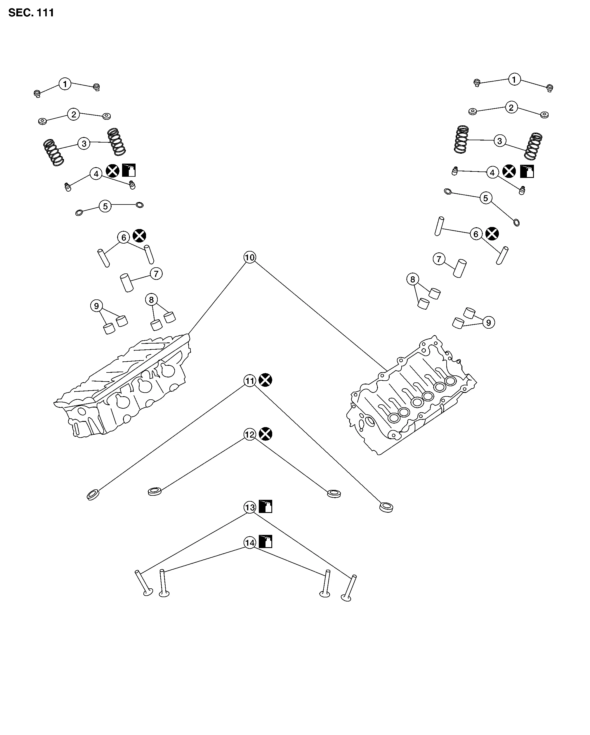
| 1. | Valve collet | 2. | Valve spring retainer | 3. | Valve spring |
| 4. | Valve oil seal | 5. | Valve spring seat | 6. | Valve guide |
| 7. | Spark plug tube | 8. | Lifter (INT) | 9. | Lifter (EXH) |
| 10. | Cylinder head | 11. | Valve seat (EXH) | 12. | Valve seat (INT) |
| 13. | Valve (EXH) | 14. | Valve (INT) |
CAUTION:
-
When installing camshafts, chain tensioners, oil seals, or other sliding parts, lubricate contacting surfaces with new engine oil.
-
Apply new engine oil to threads and seat surface when installing cylinder head, camshaft sprocket, crankshaft pulley, and camshaft bracket.
-
Attach tags to valve lifters so as not to mix them up.
DISASSEMBLY
Remove spark plug. Refer to Removal and Installation.
Remove valve lifter.
-
Identify installation positions and store them without mixing them up.
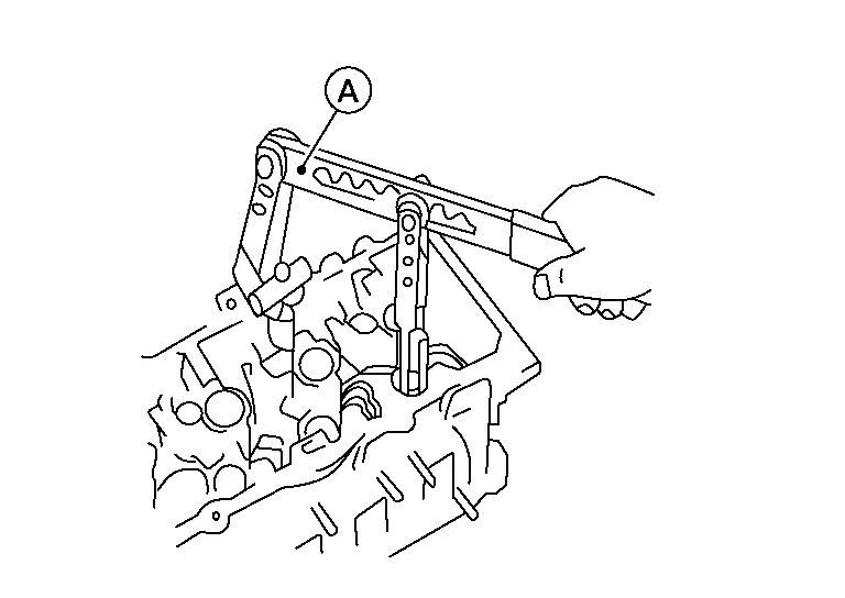
Remove valve collet.
-
Compress valve spring using suitable tool (A) and remove valve collet with magnet hand.
CAUTION:
Be careful not to damage valve lifter bore.
Remove valve spring retainer, valve spring and valve spring seat.
Push valve stem to combustion chamber side and remove valve.
-
Identify installation positions, and store them without mixing them up.
Remove valve oil seals using suitable tool (A).

Remove valve seat (if necessary). Refer to Inspection After Disassembly.
Remove valve guide (if necessary). Refer to Inspection After Disassembly.
Remove spark plug tube. (if necessary).
-
Using pair of pliers, pull spark plug tube out of cylinder head.
CAUTION:
-
Take care not to damage cylinder head.
-
Once removed, spark plug tube will be deformed and cannot be reused. Do not remove it unless absolutely necessary.
ASSEMBLY
Install valve guide (if removed). Refer to Inspection After Disassembly.
Install valve seat (if removed). Refer to Inspection After Disassembly.
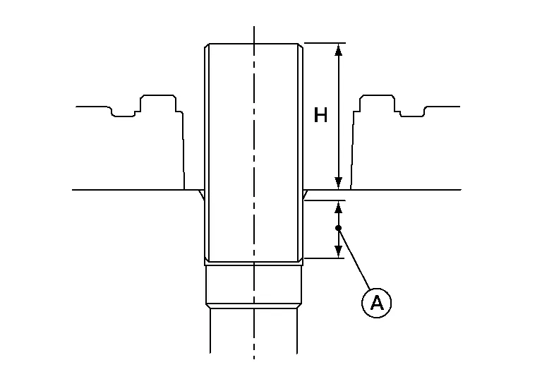
Install valve oil seals using suitable tool (A).

| Height (H) (Without valve spring seat installed) | ||
| Intake and exhaust | : 14.3 - 14.9 mm (0.563 - 0.587 in) | |
Install valve spring seat.
Install valves.
-
Install it in the original position.
 NOTE:
NOTE:
Larger diameter valves are for intake side.
Install valve spring (uneven pitch type) with narrow pitch (C) end (paint mark) (B) facing cylinder head side (A). Wide pitch (D) end should face away from cylinder head.
Install valve spring retainer.
Install valve collet.
-
Compress valve spring using suitable tool (A), attachment and adapter. Install valve collet with magnet hand.
CAUTION:
When working, take care not to damage valve lifter bore.
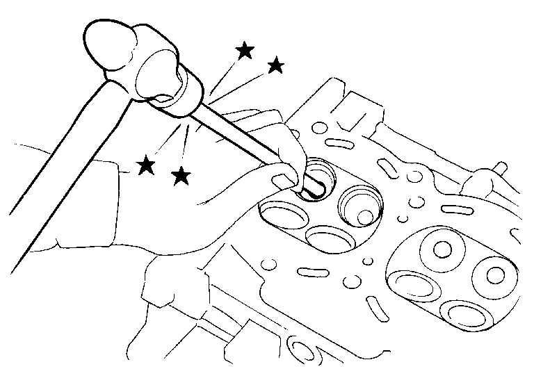
-
Tap valve stem edge lightly with plastic hammer after installation to check its installed condition.
Install valve lifter.
-
Install it in the original position.
Install spark plug tube.
-
Press-fit spark plug tube as follows:
Use Genuine High Strength Locking Sealant or equivalent. Refer to Recommended Chemical Products and Sealants.
Press-fit spark plug tube so that its height (H) is as specified in using suitable tool. Refer to Cylinder Head.CAUTION:
-
When press-fitting, take care not to deform spark plug tube.
-
After press-fitting, wipe off liquid gasket protruding onto cylinder-head upper face.
Install spark plug. Refer to Removal and Installation.
CYLINDER HEAD DISTORTION
Clean the surface of the cylinder head. Use a reliable straightedge and feeler gauge to check the flatness of cylinder head surface.
Check along six positions as shown. Refer to Disassembly and Assembly.
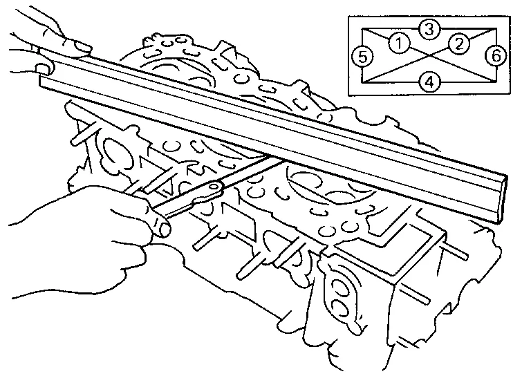
If it exceeds the limit, replace the cylinder head.
The limit for cylinder head resurfacing is determined by the cylinder block resurfacing. Refer to Cylinder Head.
After resurfacing cylinder head, check that camshaft rotates freely by hand. If resistance is felt, cylinder head must be replaced.
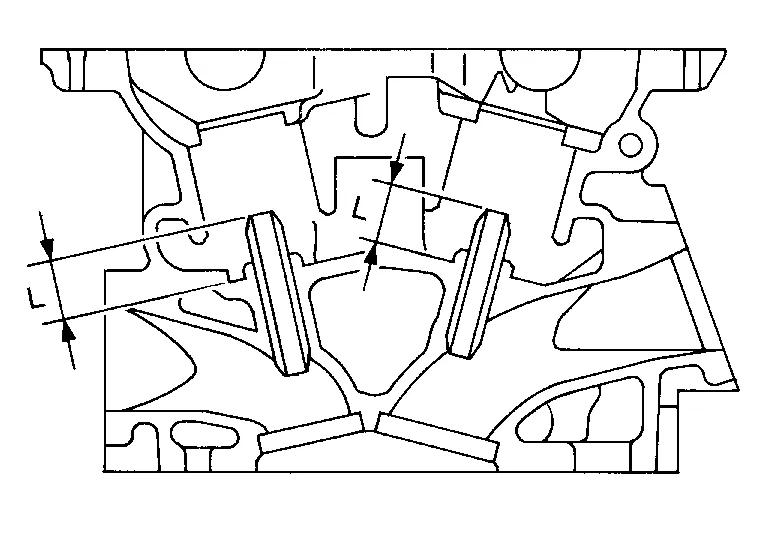
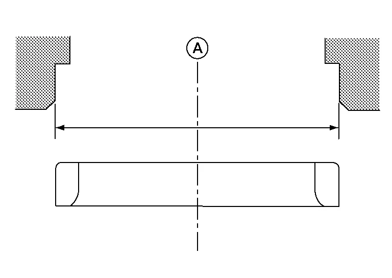
VALVE GUIDE CLEARANCE
Measure valve deflection (D) using a suitable tool (C) as shown (Valve and valve guide mostly wear in this direction). Measuring direction (E) should be 90° (B) of camshaft direction (A). Refer to Cylinder Head.
| Maximum deflection | : 0.25 mm (0.010 in) |
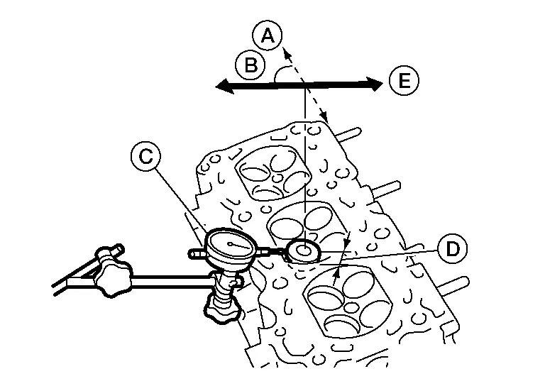
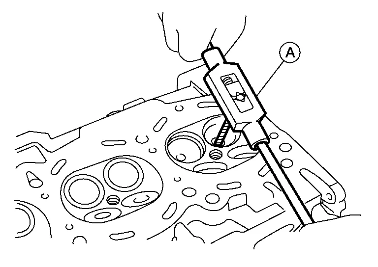
If it exceeds the limit, check valve to valve guide clearance with a suitable tool (A).
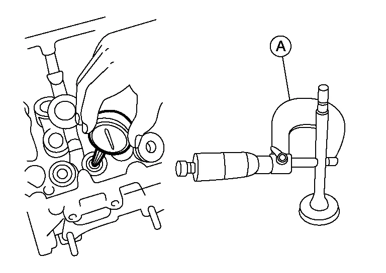
(Valve guide clearance) = (Valve guide inner diameter) - (Valve stem diameter). Refer to Cylinder Head.
If it exceeds the limit, replace valve or valve guide.VALVE GUIDE REPLACEMENT
When valve guide is removed, replace with oversized [0.2 mm (0.008 in)] valve guide.
To remove valve guide, heat cylinder head to 110 - 130°C (230 - 266°F) by soaking in heated oil (A).
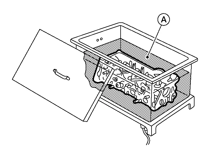
WARNING:
Cylinder head contains heat. When working, wear protective equipment to avoid getting burned.
Drive out the valve guide with a press [under a 20 kN (2.2 US ton) pressure] or hammer and suitable tool.
Ream cylinder head valve guide hole using suitable tool (A). Refer to Cylinder Head.
Heat cylinder head to 110 - 130°C (230 - 266°F) by soaking in heated oil and press new valve guide from camshaft side into the cylinder head to the dimensions as shown. Refer to Cylinder Head.
WARNING:
Cylinder head contains heat. When working, wear protective equipment to avoid getting burned.
Using a suitable tool (A), apply a reamer finish to the valve guide.
| Intake and exhaust finished size |
: 6.000 - 6.018 mm (0.2362 - 0.2369 in) |
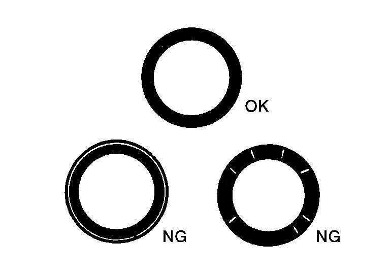
VALVE SEAT CONTACT
-
After confirming that the dimensions of valve guides and valves are within specifications, perform this procedure.
-
Apply Prussian blue onto contacting surface of valve seat to check the condition of the valve contact on the surface.
-
Check if the contact area band is continuous all around the circumference.
-
If not, grind to adjust valve fitting and check again. If the contacting surface still has NG conditions even after the recheck, replace valve seat.
VALVE SEAT REPLACEMENT
Bore out old seat (A) until it collapses. Boring should not continue beyond the bottom face of the seat recess in cylinder head. Set the machine depth stop to ensure this.
Ream cylinder head recess for service valve seat. Refer to Cylinder Head.
CAUTION:
Be sure to ream in circles concentric to the valve guide center. This will enable valve seat to fit correctly.
Heat cylinder head to 110 - 130°C (230 - 266°F) by soaking in heated oil (A).
WARNING:
Cylinder head contains heat. When working, wear protective equipment to avoid getting burned.
Press fit valve seat until it seats on the bottom.
Cut or grind valve seat using suitable tool to the specified dimensions. Refer to Cylinder Head.
After cutting, lap valve seat with abrasive compound.
Check valve seating condition. Refer to Cylinder Head.
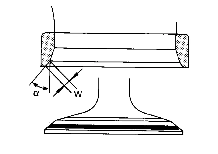
Use a depth gauge to measure the distance between the mounting surface of the cylinder head spring seat and the valve stem end on the exhaust (A) and intake (B) sides. If the distance is shorter than specified, repeat step 5 to adjust it. If it is longer, replace the valve seat with a new one. Refer to Cylinder Head.
VALVE SPRING SQUARENESS
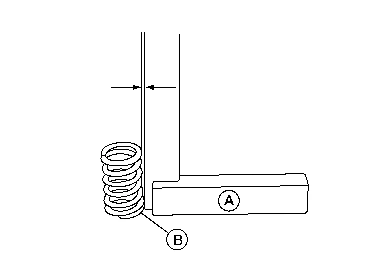
Set try square (A) along the side of valve spring and rotate the spring. Valve spring should contact (B) the try square (A) (Measure the maximum clearance between the top face of spring and try square. Refer to Cylinder Head.
VALVE SPRING DIMENSIONS AND VALVE SPRING PRESSURE LOAD
Check valve spring pressure at specified spring height.
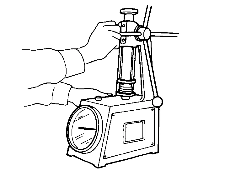
If it is not within specifications, replace the spring. Refer to Cylinder Head.
 Oil Seal
Removal and Installation of Valve Oil Seal
REMOVALTurn crankshaft until the cylinder requiring new oil seals is at TDC. This will prevent valve from dropping into cylinder...
 Engine Mount. Engine Mount (front)
Removal and Installation
WARNING:
Situate the vehicle on a flat and solid surface.
Place chocks at front and back of rear wheels.
CAUTION:
Always work safely...
Other information:
Nissan Murano (Z52) 2015-2024 Service Manual: U1010 Control Unit(can)
DTC Description DESCRIPTIONAir bag diagnosis sensor unit performs self-tests at ignition switch ON. If CAN communication failure within control unit is detected, DTC is set.DTC DETECTION LOGIC DTC No. CONSULT screen items (Trouble diagnosis content) DTC detecting condition U1010-49 CONTROL UNIT(CAN) Diagnosis condition When ignition switch is ON...
Nissan Murano (Z52) 2015-2024 Service Manual: Spark Plug
Exploded View 1. Ignition coil 2. Spark plug 3. Rocker cover (RH) 4. Rocker cover (LH) Front Removal and Installation REMOVALRemove the ignition coil. Refer to Removal and Installation (bank 2) and Removal and Installation (bank 1)...
Categories
- Manuals Home
- Nissan Murano Owners Manual
- Nissan Murano Service Manual
- System malfunction
- Vehicle Dynamic Control (VDC) OFF switch
- How to enable/disable the LDW system
- New on site
- Most important about car
LATCH (Lower Anchors and Tethers for CHildren) system

LATCH system lower anchor locations - bench seat
Your vehicle is equipped with special anchor points that are used with LATCH system compatible child restraints. This system may also be referred to as the ISOFIX or ISOFIX compatible system. With this system, you do not have to use a vehicle seat belt to secure the child restraint unless the combined weight of the child and child restraint exceeds 65 lbs. (29.5 kg). If the combined weight of the child and child restraint is greater than 65 lbs. (29.5 kg), use the vehicle’s seat belt (not the lower anchors) to install the child restraint. Be sure to follow the child restraint manufacturer’s instructions for installation.