Nissan Murano: Engine Mechanical :: Removal and Installation / Oil Seal
REMOVAL
Turn crankshaft until the cylinder requiring new oil seals is at TDC. This will prevent valve from dropping into cylinder.
CAUTION:
When rotating crankshaft, be careful to avoid scarring the front cover with the timing chain.
Remove camshaft relating to valve oil seal to be removed. Refer to Removal and Installation.
Remove valve lifters.
Remove valve collet, valve spring retainer and valve spring using suitable tool (A).
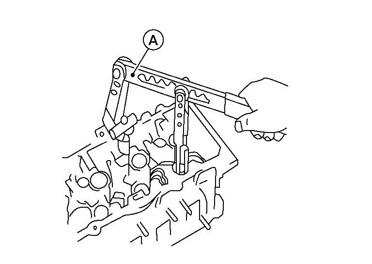
CAUTION:
Be careful not to damage valve lifter bore.
-
Compress valve spring using suitable tool, attachment and adapter. Remove valve collet with magnet hand.
Remove valve oil seal using suitable tool (A).

INSTALLATION
Apply new engine oil to new valve oil seal joint surface and seal lip.
Press in valve oil seal to height (H) using suitable tool (A).

 NOTE:
NOTE:
Dimension (H): height measured before valve spring seat installation.
| Intake and exhaust (H) | : 14.3 - 14.9 mm (0.563 - 0.587 in) |
Installation of the remaining components is in the reverse order of removal.
REMOVAL
Remove drive belt. Refer to Removal and Installation.
Lock the drive plate using Tool.
| Tool number | : — (J-50288) |
CAUTION:
Do not damage the ring gear teeth or the signal plate teeth behind the ring gear when setting the Tool.
Remove the crankshaft pulley as follows:Loosen crankshaft pulley and locate bolt seating surface at 10 mm (0.39 in) from its original position. Position a pulley puller at recess hole of crankshaft pulley to remove crankshaft pulley.

CAUTION:
Do not use a puller claw on the outer diameter of the crankshaft pulley.
Remove front oil seal from front cover using a suitable tool.

CAUTION:
Be careful not to damage front cover or crankshaft.
INSTALLATION
Apply new engine oil to oil seal lip (C) and dust seal (D) and install.

-
Install new oil seal towards the engine inside (B) as shown.
CAUTION:
-
Press fit straight and avoid causing burrs to engine inside (C) or engine outside (A) or tilting the oil seal.
-
Do not reuse front oil seal.
-
Press-fit oil seal until it becomes flush with the timing chain case end face, using Tool (A).

Tool number (A) : — (J-37066) -
Make sure the garter spring in the oil seal is in position and seal lip is not inverted.
Install crankshaft pulley and tighten the bolt in two steps.
-
Lubricate thread and seat surface of the bolt with new engine oil.
-
For the second step angle tighten using Tool.
CAUTION:
-
Do not damage the front oil seal when inserting crankshaft pulley.
-
Use only brass or plastic hammer if tapping on the crankshaft pulley.
-
Do not hammer on pulley grooves.
| Step 1 | : 44.1 N·m (4.5 kg-m, 33 ft-lb) |
| Step 2 | : 90°(+0°/-6°) degrees clockwise |
| Tool number | : KV10112100 (BT-8653-A) |
Remove the Tool to unlock the drive plate.
| Tool number | : — (J-50288) |
CAUTION:
Do not damage the ring gear teeth, or the signal plate teeth behind the ring gear, when removing the Tool.
Installation of the remaining components is in the reverse order of removal.
REMOVAL
Remove the upper oil pan. Refer to Removal and Installation (Upper Oil Pan).
Remove drive plate. Refer to Exploded View.
Remove rear oil seal retainer using Tool (A).

| Tool Number (A) | : KV10111100 (J-37228) |
CAUTION:
-
Be careful not to damage mating surface.
-
If rear oil retainer is removed, replace it with a new one
NOTE:
Rear oil seal and retainer form a single part and are replaced as an assembly.
INSTALLATION
Remove old liquid gasket material from mating surface of cylinder block and oil pan using a suitable scraper.
Install the rear oil seal using Tool (A).
CAUTION:
Do not reuse rear oil seal.

| Tool number (A) | : — (J-47128) |

Use Genuine Silicone RTV Sealant or equivalent. Refer to Recommended Chemical Products and Sealants.
CAUTION:
-
Installation should be done within 5 minutes after applying liquid gasket.
-
Do not fill the engine with oil for at least 30 minutes after the components are installed to allow the liquid gasket to cure.

| Rear oil seal retainer bolts | : 8.8 N·m (0.9 kg-m, 78 in-lb) |
Installation of the remaining components is in the reverse order of removal.
CAUTION:
-
When replacing an engine or transmission you must make sure the dowels are installed correctly during reassembly.
-
Improper alignment caused by missing dowels may cause vibration, oil leaks or breakage of drivetrain components.
 Camshaft
Exploded View
1.
Camshaft position sensor bracket (bank 1)
2.
Camshaft brackets
3.
No. 1 camshaft bracket (bank 1)
4.
Camshaft (EXH) (bank 1)
5...
 Cylinder Head
Exploded View
1.
Cylinder head bolt
2.
Cylinder head
3.
Cylinder head gasket
4.
Engine block
A.
Refer to Removal and Installation.
Removal and Installation
REMOVALRemove the engine from the vehicle...
Other information:
Nissan Murano (Z52) 2015-2024 Service Manual: Headlamp Function
Component Function Check CHECK FUNCTION CONSULT Select the "HEAD LAMP(HI)" in "Active Test" mode of "BCM(THEFT ALM)". Check headlamps operation. Test item Description HEAD LAMP (HI) ON Headlamps (Hi) Light OFF Do not light Is the inspection result normal? YES>> Inspection End...
Nissan Murano (Z52) 2015-2024 Service Manual: B2667 Pass Sunload Sensor
DTC Description DTC DETECTION LOGICNOTE: If DTC is displayed along with DTC U1000 or U1010, first diagnose the DTC U1000 or U1010. Refer to DTC Description (U1000) or DTC Description (U1010). Sunload sensor may register a malfunction when indoors, at dusk, or at other times when light is insufficient...
Categories
- Manuals Home
- Nissan Murano Owners Manual
- Nissan Murano Service Manual
- How to enable/disable the LDW system
- Intelligent Forward Collision Warning (I-FCW)
- Power Steering Fluid (PSF)
- New on site
- Most important about car