Nissan Murano: Component Parts / Cvt Control System
 |
CVT shift selector assembly |  |
Combination meter |  |
Behind of combination meter |
 |
Engine room (RH side) |  |
Engine room (LH side) |  |
Transaxle assembly |
COMPONENT DESCRIPTION
| No. | Component | Function | |
|---|---|---|---|
 |
Manual mode switch | Manual Mode Switch | |
 |
Combination meter |
Mainly transmits the following signal to TCM via CAN communication
Mainly receives the following signals from TCM via CAN communication.
|
|
 |
Malfunction indicator lamp (MIL) | Malfunction Indicator Lamp (MIL) | |
 |
Shift position indicator | Shift Position Indicator | |
 |
BCM (view with combination meter removed) |
Mainly transmits the following signal to TCM via CAN communication
|
|
 |
ABS actuator and electronic unit (control unit) |
Mainly transmits the following signal to TCM via CAN communication
|
|
 |
TCM | TCM | |
 |
ECM |
Mainly transmits the following signal to TCM via CAN communication.
Mainly receives the following signals from TCM via CAN communication.
|
|
 |
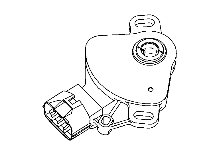
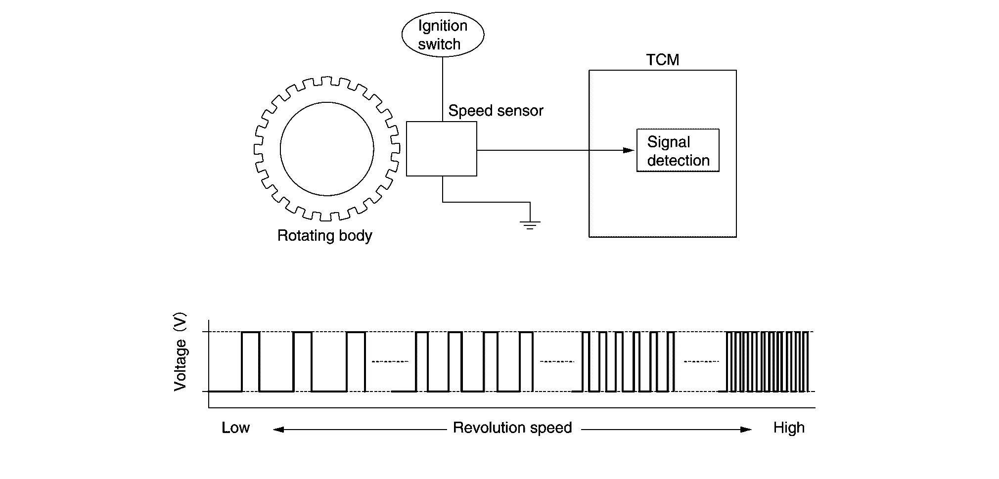
Output speed sensor | Output Speed Sensor | |
 |
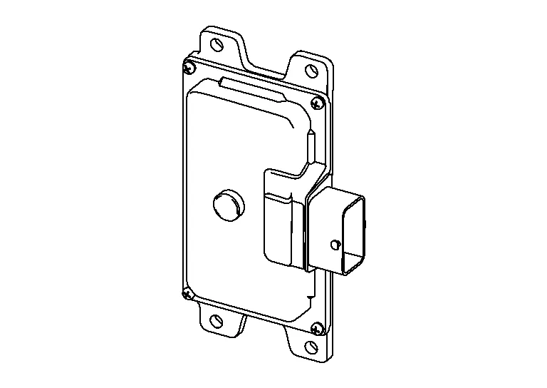
Transmission range switch | Transmission Range Switch | |
 |
Input speed sensor | Input Speed Sensor | |
 |
CVT unit connector | — | |
 |
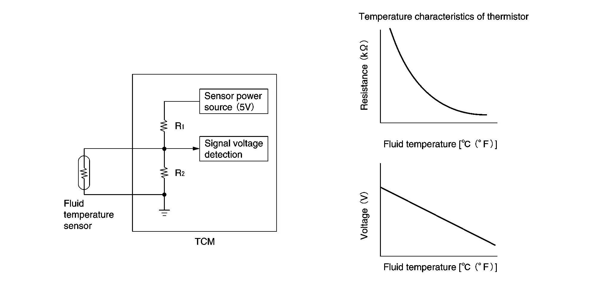
Control valve | CVT fluid temperature sensor* | CVT Fluid Temperature Sensor |
| Primary pressure sensor* | Primary Pressure Sensor | ||
| Secondary pressure sensor* | Secondary Pressure Sensor | ||
| Line pressure solenoid valve* | Line pressure solenoid valve | ||
| Primary pressure solenoid valve* | Primary pressure solenoid valve | ||
| Secondary pressure solenoid valve* | Secondary pressure solenoid valve | ||
| Torque converter clutch solenoid valve* | Torque converter clutch solenoid valve | ||
| Select solenoid valve* | Select solenoid valve | ||
 |
Primary speed sensor | Primary pressure sensor | |
*: These components are included in control valve assembly.
-
The TCM consists of a microcomputer and connectors for signal input and output and for power supply.
-
The Nissan Murano vehicle driving status is judged based on the signals from the sensors, switches, and other control units, and the optimal transaxle control is performed.
-
For TCM control items, refer to System Description.
-
The transmission range switch is installed to upper part of transaxle case.
-
The transmission range switch detects the selector lever position.
-
The input speed sensor is installed to the front side of transaxle case.
-
The input speed sensor detects input shaft speed.
-
The input speed sensor generates an ON-OFF pulse signal according to the rotating body speed. TCM judges the rotating body speed from the pulse signal.
-
The primary speed sensor is installed to transaxle side cover.
-
The primary speed sensor detects primary pulley speed.
-
The primary speed sensor generates an ON-OFF pulse signal according to the rotating body speed. TCM judges the rotating body speed from the pulse signal.
-
The output speed sensor is installed to the back side of transaxle case.
-
The output speed sensor detects final gear speed.
-
The output speed sensor generates an ON-OFF pulse signal according to the rotating body speed. TCM judges the rotating body speed from the pulse signal.
-
The CVT fluid temperature sensor is installed to control valve.
-
The CVT fluid temperature sensor detects CVT fluid temperature in oil pan.
-
The fluid temperature sensor uses a thermistor, and changes the signal voltage by converting changes in the CVT fluid temperature to a resistance value. TCM evaluates the CVT fluid temperature from the signal voltage value.
-
The primary pressure sensor is installed to control valve.
-
The primary pressure sensor detects the pressure applied to the primary pulley.
-
When pressure is applied to the ceramic device in the primary pressure sensor, the ceramic device is deformed, resulting in voltage change. TCM evaluates the primary pressure from its voltage change. Voltage is increased along with pressure increase.
-
The secondary pressure sensor is installed to control valve.
-
The secondary pressure sensor detects the pressure applied to the secondary pulley.
-
When pressure is applied to the ceramic device in the secondary pressure sensor, the ceramic device is deformed, resulting in voltage change. TCM evaluates the secondary pressure from its voltage change. Voltage is increased along with pressure increase.
-
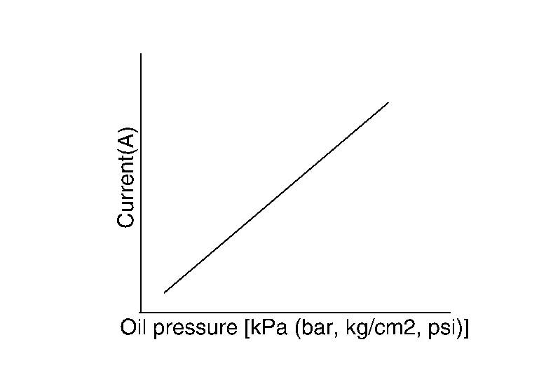
The line pressure solenoid valve is installed to control valve.
-
The line pressure solenoid valve controls the pressure regulator valve. For information about the pressure regulator valve, refer to Oil Pressure System.
-
The line pressure solenoid valve uses the linear solenoid valve [N/H (normal high) type].

 NOTE:
NOTE:
-
The principle of the linear solenoid valve utilizes the fact that the force pressing on the valve spool installed inside the coil increases nearly in proportion to the current. This allows it to produce a fluid pressure that is proportional to this pressing force.
-
The N/H (normal high) produces hydraulic control when the coil is not energized.
-
-
The primary pressure solenoid valve is installed to control valve.
-
The primary pressure solenoid valve controls the primary reducing valve. For information about the primary reducing valve, refer to Oil Pressure System.
-
The primary pressure solenoid valve uses the linear solenoid valve [N/H (normal high) type].
NOTE:
-
The principle of the linear solenoid valve utilizes the fact that the force pressing on the valve spool installed inside the coil increases nearly in proportion to the current. This allows it to produce a fluid pressure that is proportional to this pressing force.
-
The N/H (normal high) produces hydraulic control when the coil is not energized.
-
-
The secondary pressure solenoid valve is installed to control valve.
-
The secondary pressure solenoid valve controls the secondary reducing valve. For information about the secondary reducing valve, refer to Component Description.
-
The secondary pressure solenoid valve uses the linear solenoid valve [N/H (normal high) type].
NOTE:
-
The principle of the linear solenoid valve utilizes the fact that the force pressing on the valve spool installed inside the coil increases nearly in proportion to the current. This allows it to produce a fluid pressure that is proportional to this pressing force.
-
The N/H (normal high) produces hydraulic control when the coil is not energized.
-
-
The torque converter clutch solenoid valve is installed to control valve.
-
The torque converter clutch solenoid valve controls the torque converter clutch control valve. For information about the torque converter clutch control valve, refer to Oil Pressure System.
-
The torque converter clutch solenoid valve utilizes a linear solenoid valve [N/L (normal low) type].
 NOTE:
NOTE:
-
The principle of the linear solenoid valve utilizes the fact that the force pressing on the valve spool installed inside the coil increases nearly in proportion to the current. This allows it to produce a fluid pressure that is proportional to this pressing force.
-
The N/L (normal low) type does not produce hydraulic control when the coil is not energized.
-
-
The select solenoid valve is installed to control valve.
-
The select solenoid valve adjusts the tightening pressure of the forward clutch and reverse brake.
-
The select solenoid valve uses the linear solenoid valve [N/H (normal high) type].
NOTE:
-
The principle of the linear solenoid valve utilizes the fact that the force pressing on the valve spool installed inside the coil increases nearly in proportion to the current. This allows it to produce a fluid pressure that is proportional to this pressing force.
-
The N/H (normal high) produces hydraulic control when the coil is not energized.
-
-
The manual mode switch is installed in the CVT shift selector assembly.
-
The manual mode switch detects the position (the main shift gate side or manual shift gate side) of the selector lever and transmits a manual mode signal or a not manual mode signal to the combination meter. Then, the TCM receives a manual mode signal or non-manual mode signal from the combination meter.
-
The manual mode switch detects that the selector lever is shifted to the shift-up side of the manual shift gate and transmits a manual mode shift up signal to the combination meter. Then, the TCM receives a manual mode shift up signal from the combination meter.
-
The manual mode switch detects that the selector lever is shifted to the shift-down side of the manual shift gate and transmits a manual mode shift down signal to the combination meter. Then, the TCM receives a manual mode shift down signal from the combination meter.
TCM transmits shift position signal to combination meter via CAN communication. The actual shift position is displayed on combination meter according to the signal.
The malfunction indicator lamp (MIL) is located on the combination meter.
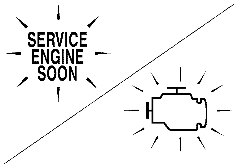
The MIL will illuminate when the ignition switch is turned ON without the engine running. This is a bulb check.
When the engine is started, the MIL should turn off. If the MIL remains illuminated, the on board diagnostic system has detected an engine system malfunction.
For details, refer to Malfunction Indicator Lamp (MIL).

 Shift Lock System
Component Parts Location
A.
Between front seats (view with center console removed)
B.
View with instrument panel removed
C.
Brake pedal area
No...
Other information:
Nissan Murano (Z52) 2015-2024 Service Manual: Malfunction Area Chart
Vehicle CAN Communication Circuit MAIN LINE Malfunction area Reference Main line between IPDM E/R and ABS actuator and electric unit (control unit) Diagnosis Procedure Main line between ABS actuator and electric unit (control unit) and A/C auto amp...
Nissan Murano (Z52) 2015-2024 Service Manual: Moonroof
Diagnosis Procedure PERFORM INITIALIZATION PROCEDURE Perform initialization procedure. Refer to Special Repair Requirement. Is the inspection result normal? YES>> GO TO 2. NO>> Perform basic inspection. Refer to Work Flow. RETEST THE ANTI-PINCH FUNCTION Check anti-pinch operation...
Categories
- Manuals Home
- Nissan Murano Owners Manual
- Nissan Murano Service Manual
- Vehicle Dynamic Control (VDC) OFF switch
- System malfunction
- High Beam Assist (if so equipped)
- New on site
- Most important about car
Driver and passenger supplemental knee air bag

Driver’s side
The knee air bag is located in the knee bolster, on the driver’s and passenger’s side. All of the information, cautions and warnings in this manual apply and must be followed. The knee air bag is designed to inflate in higher severity frontal collisions, although it may inflate if the forces in another type of collision are similar to those of a higher severity frontal impact. It may not inflate in certain collisions.

Passenger’s side