Nissan Murano: System Description / Component Parts. Power Distribution System
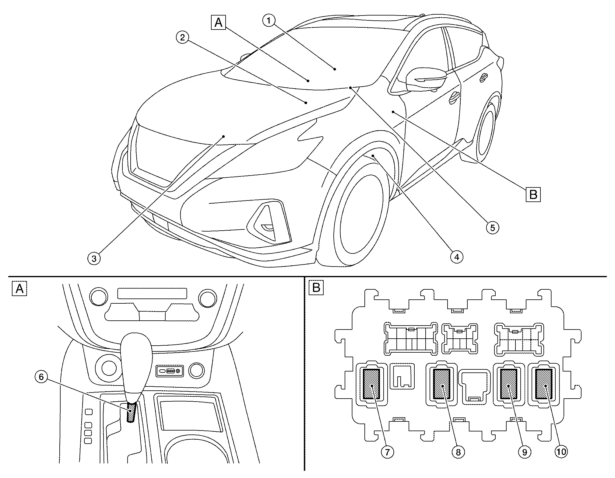
| A. | Front of center console | B. | Instrument lower panel LH |
| No. | Component | Function |
|---|---|---|
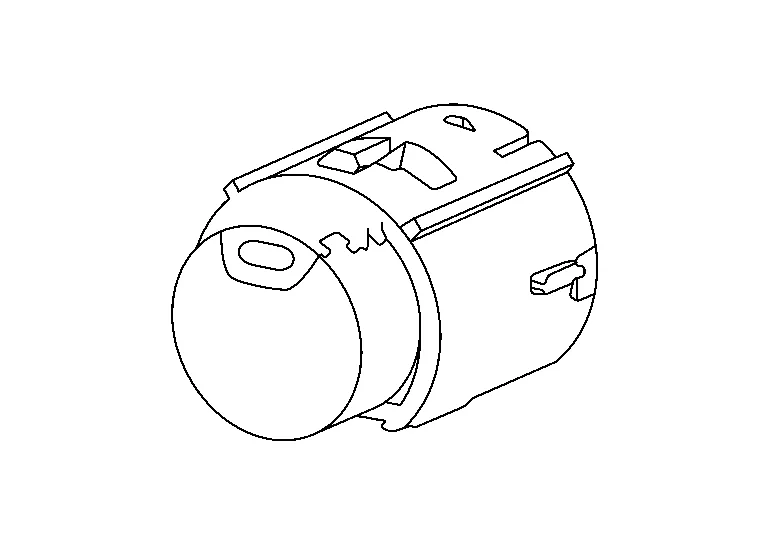
| 1. | Push-button ignition switch | Refer to Push-Button Ignition Switch. |
| 2. |
IPDM E/R (Intelligent Power Distribution Module Engine Room) |
|
| 3. | Transmission range switch |
The transmission range switch detects the selector lever position. Refer to Transmission Range Switch for detailed component location. |
| 4. | Stop lamp switch |
Stop lamp switch detects that brake pedal is depressed, and transmits the signal to BCM. Refer to Brake Pedal Position Switch / Stop Lamp Switch for detailed component location. |
| 5. |
BCM (Body Control Module) |
|
| 6. |
CVT shift selector (detent switch) |
CVT shift selector (detent switch) detects shift lever status, transmits detention switch signal to BCM. Refer to Component Parts Location for detailed component location. |
| 7. | Ignition relay-2 [in fuse block (J/B)] |
|
| 8. | Front blower motor relay [in fuse block (J/B)] |
|
| 9. | Rear window defogger relay [in fuse block (J/B)] | Operates the rear window defogger and the door mirror defogger with the control signal from BCM. |
| 10. | Accessory relay-1 [in fuse block (J/B)] |
|
-
Push-button ignition switch is installed in the console.
-
Push-button ignition switch is pressed, and transmits the status signal to BCM and IPDM E/R.

 System. Power Distribution System
System Description
SYSTEM DIAGRAMSignal transmission function list Signal name Input Output Description
Push-button ignition switch signal
Push-button ignition switch
BCM
Transmits the push-button ignition switch signal to the BCM...
Other information:
Nissan Murano (Z52) 2015-2024 Owners Manual: Spare tire (TEMPORARY USE ONLY spare tire)
When replacing a wheel without the TPMS such as the spare tire, the TPMS will not function. Observe the following precautions if the TEMPORARY USE ONLY spare tire must be used. Otherwise, your vehicle could be damaged or involved in an accident: WARNING The spare tire should be used for emergency use only...
Nissan Murano (Z52) 2015-2024 Service Manual: Fluid Cooler Hose
Exploded View 1. Transaxle assembly 2. Hose clamp 3. CVT fluid cooler hose A 4. Hose clip 5. CVT fluid cooler hose B 6. Connector tube 7. CVT fluid cooler hose C 8 Oil warmer A. To radiator. Refer to Exploded View...
Categories
- Manuals Home
- Nissan Murano Owners Manual
- Nissan Murano Service Manual
- Turning the AEB system on/off
- GAS STATION INFORMATION
- Checking engine oil level
- New on site
- Most important about car
Luggage hooks

When securing items using luggage hooks located on the back of the seat or side finisher do not apply a load over more than 6.5 lbs. (29 N) to a single hook.
The luggage hooks that are located on the floor should have loads less than 110 lbs. (490 N) to a single hook.