Nissan Murano: System Description / System. Power Distribution System
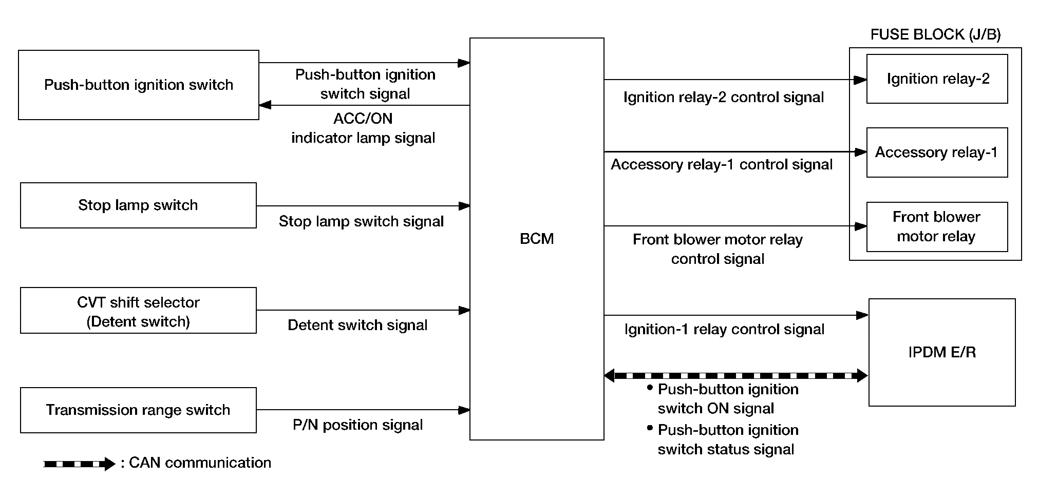
SYSTEM DIAGRAM
Signal transmission function list
| Signal name | Input | Output | Description |
|---|---|---|---|
| Push-button ignition switch signal | Push-button ignition switch | BCM | Transmits the push-button ignition switch signal to the BCM. |
| ACC/ON indicator lamp signal | BCM | Push-button ignition switch | Activates/deactivates push-button ignition switch illumination using the ACC/ON indicator lamp signal. |
| Stop lamp switch signal | Stop lamp switch | BCM | Transmits the stop lamp switch signal to the BCM. |
| Detent switch signal | CVT shift selector (detent switch) | BCM | Transmits the detent switch signal to the BCM. |
| P/N position signal | Transmission range switch | BCM | Transmits the P/N position signal to the BCM. |
| Ignition relay-1 control signal | BCM | IPDM E/R | Transmits the ignition relay-1 control signal to the IPDM E/R. |
| Push-button ignition switch ON signal | BCM | IPDM E/R (CAN) | Transmits the push-button ignition switch ON signal via CAN communication. |
| Push-button ignition switch status signal | IPDM E/R | BCM (CAN) | Transmits the push-button ignition switch status signal via CAN communication. |
SYSTEM DESCRIPTION
-
PDS (POWER DISTRIBUTION SYSTEM) is the system that BCM controls with the operation of the push-button ignition switch and performs the power distribution to each power circuit. This system is used instead of the mechanical power supply changing mechanism with the operation of the conventional key cylinder.
-
The push-button ignition switch can be operated when Intelligent Key is in the following condition:
-
Intelligent Key is in the detection area of the inside key antenna.
-
Intelligent Key backside is contacted to push-button ignition switch.
-
-
The push-button ignition switch operation is input to BCM as a signal. BCM changes the power supply position according to the status of the push-button ignition switch and operates the following relays to supply power to each power circuit:
-
Ignition relay-1 (IPDM E/R)
-
Ignition relay-2 [Fuse block (J/B)]
-
Accessory relay-1 [Fuse block (J/B)]
-
Front blower motor relay [Fuse block (J/B)]
 NOTE:
NOTE:
The engine switch operation changes due to the conditions of brake pedal, selector lever and Nissan Murano vehicle speed.
-
-
The power supply position can be confirmed with the lighting of the indicators in the push-button ignition switch.
IGNITION BATTERY SAVER SYSTEM
When all the following conditions are met for a period of time, the battery saver system will turn off the power supply (push-button ignition switch ON/ACC → OFF) to prevent battery discharge:
-
Push-button ignition switch is in ACC or ON
-
Turn signal lamp is not in operation
-
Selector lever is in the P (park) position
Reset Condition of Ignition Battery Saver System
If any of the following conditions are met, the battery saver system is released:
-
Push-button ignition switch is not in ACC or ON
-
Turn signal lamp is in operation
-
Selector lever is not in the P (park) position
NOTE:
The ignition battery saver system can be temporarily disabled, without using CONSULT, to prevent it from functioning when performing trouble diagnosis. Refer to Work Procedure.
POWER SUPPLY POSITION CHANGE TABLE BY PUSH-BUTTON IGNITION SWITCH OPERATION
The power supply position changing operation can be performed with the following operations:
NOTE:
-
When an Intelligent Key is within the detection area of inside key antenna and when Intelligent Key backside is contacted to push-button ignition switch, it is equivalent to the operations below.
-
When starting the engine, the BCM monitors under the engine start conditions:
-
Brake pedal operating condition
-
Selector lever position
-
Nissan Murano Vehicle speed
-
Vehicle speed: less than 2.5 MPH (4 km/h)
| Power supply position | Engine start/stop condition | Push-button ignition switch operation frequency | |
|---|---|---|---|
| Selector lever position | Brake pedal operation condition | ||
| OFF → ACC | — | Not depressed | 1 |
| OFF → ACC → ON | — | Not depressed | 2 |
| OFF → ACC → ON → OFF | — | Not depressed | 3 |
|
OFF → START ACC → START ON → START |
P or N position | Depressed | 1 |
| Engine is running → OFF | — | — | 1 |
Vehicle speed: 2.5 MPH (4 km/h) or more
| Power supply position | Engine start/stop condition | Push-button ignition switch operation frequency | |
|---|---|---|---|
| Selector lever position | Brake pedal operation condition | ||
| Engine is running → ACC | — | — | Emergency stop operation |
| Engine stall return operation while driving | N position | Not depressed | 1 |
Emergency stop operation
-
Press and hold the push-button ignition switch for 2 seconds or more.
-
Press the push-button ignition switch 3 times or more within 1.5 seconds.
 Component Parts. Power Distribution System
Component Parts Location
A.
Front of center console
B.
Instrument lower panel LH
No. Component Function
1.
Push-button ignition switch
Refer to Push-Button Ignition Switch...

Other information:
Nissan Murano (Z52) 2015-2024 Service Manual: Steering Switches
Exploded View 1. Steering wheel 2. Cover 3. Steering switches 4. Driver air bag module A. Refer to Exploded View. Pawl Removal and Installation REMOVALNOTE: The steering switches is serviced as an assembly. Remove steering wheel...
Nissan Murano (Z52) 2015-2024 Service Manual: C1b51-16 Blind Spot Warning Indicator Short Circuit
DTC Description DTC DETECTION LOGIC DTC No. CONSULT screen terms (Trouble diagnosis content) DTC detection condition C1B51-16 BSW/BSI IND SHORT CIR (Blind Spot Warning indicator short circuit) Diagnosis condition When ignition switch is ON. Signal (terminal) – Threshold Short circuit in Blind Spot Warning indicator circuit is detected...
Categories
- Manuals Home
- Nissan Murano Owners Manual
- Nissan Murano Service Manual
- Tire rotation
- System malfunction
- GAS STATION INFORMATION
- New on site
- Most important about car
Front manual seat adjustment (if so equipped)
Your vehicle seats can be adjusted manually. For additional information about adjusting the seats, refer to the steps outlined in this section.
Forward and backward
