Nissan Murano: Meter, Warning Lamp & Indicator :: System Description / Component Parts. Meter System
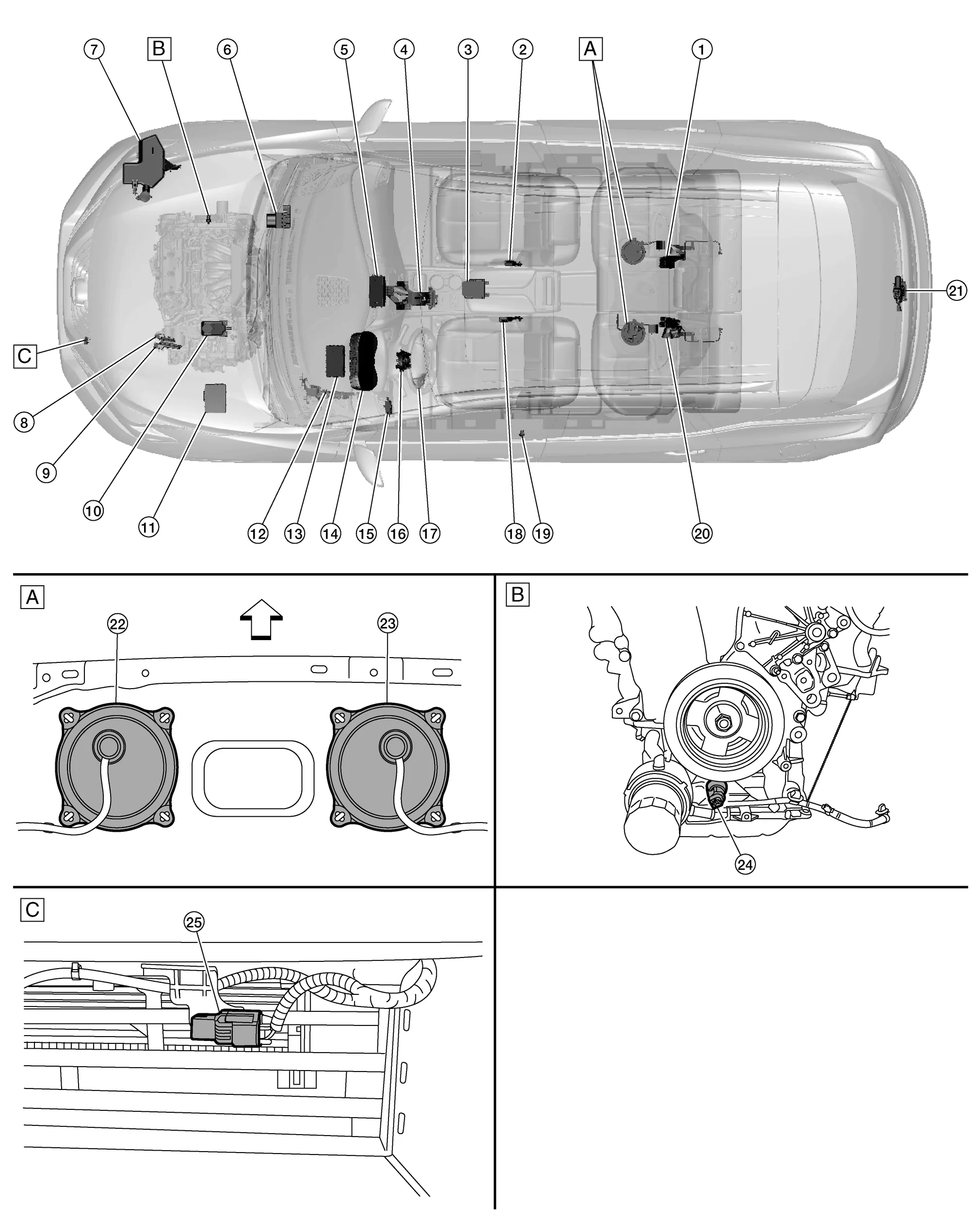
| :Nissan Murano Vehicle front | |||||
| A. | View of the inspection hole covers with the second row seat removed | B. | View of engine assembly removed | C. | View with front bumper fascia removed |
| No. | Component | Function |
|---|---|---|
| 1. | Rear seat belt buckle switch RH & CTR | Transmits the rear seat belt buckle switch RH & CTR signal to the air bag diagnosis sensor unit. |
| 2. | Front seat belt buckle switch RH | Transmits the front seat belt buckle switch RH signal to the combination meter. |
| 3. | Air bag diagnosis sensor unit |
Transmits the rear seat belt buckle switch LH and rear seat belt buckle switch RH & CTR signals to the combination meter via CAN communication. Refer to Component Parts Location for detailed component location. |
| 4. | CVT shift selector | Transmits the CVT shift selector signal to the combination meter. |
| 5. | A/C auto amp. |
Transmits the ambient sensor signal to the combination meter via CAN communication. Refer to Component Parts Location for detailed component location. |
| 6. | ABS (Anti-lock Braking System) actuator and electric unit (control unit) |
Transmits each signal to the combination meter via CAN communication. Refer to System Description. Refer to Component Parts Location for detailed component location. |
| 7. | Washer fluid level switch |
Transmits the washer fluid level switch signal to the combination meter. Refer to Component Parts Location for detailed component location. |
| 8. | TCM (Transmission Control Module) |
Transmits each signal to the combination meter via CAN communication. Refer to System Description. Refer to Component Parts Location for detailed component location. |
| 9. | ECM (Engine Control Module) |
Transmits each signal to the combination meter via CAN communication. Refer to System Description. Refer to Component Parts Location for detailed component location. |
| 10. | Brake fluid level switch | Transmits the brake fluid level signal to the combination meter. |
| 11. | IPDM E/R (Intelligent Power Distribution Module Engine Room) |
Provides a pass-through for the ambient temperature sensor signal from the ambient temperature sensor to the A/C auto amp. Refer to Component Parts Location for detailed component location. |
| 12. | Parking brake switch | Transmits the parking brake switch signal to the combination meter. |
| 13. | BCM (Body Control Module) |
Transmits each signal to the combination meter via CAN communication. Refer to System Description. Refer to Component Parts Location for detailed component location. |
| 14. | Combination meter | Refer to System Description. |
| 15. | Meter control switch | Refer to Switch Name and Function. |
| 16. | Combination switch (spiral cable) | Provides a pass-through for the steering switch signal from the steering switches to the combination meter. |
| 17. | Steering switches | Refer to Switch Name and Function. |
| 18. | Front seat belt buckle switch LH | Transmits the front seat belt buckle switch LH signal to the combination meter. |
| 19. | Front door switch LH | Transmits the front door switch LH signal to the BCM. |
| 20. | Rear seat belt buckle switch LH | Transmits the rear seat belt buckle switch LH signal to the air bag diagnosis sensor unit. |
| 21. | Back door lock assembly (door ajar switch) | Transmits the back door ajar switch signal to the BCM. |
| 22. | Fuel level sensor unit and fuel pump (main) (fuel level sensor) | Transmits the fuel level sensor signal to the combination meter. |
| 23. | Fuel level sensor unit (sub) | Transmits the fuel level sensor signal to the combination meter. |
| 24. | Engine oil pressure sensor | Transmits the engine oil pressure sensor signal to the ECM. |
| 25. | Ambient sensor |
Transmits the ambient sensor signal to the A/C auto amp. Refer to Component Parts Location for detailed component location. |
ARRANGEMENT OF COMBINATION METER
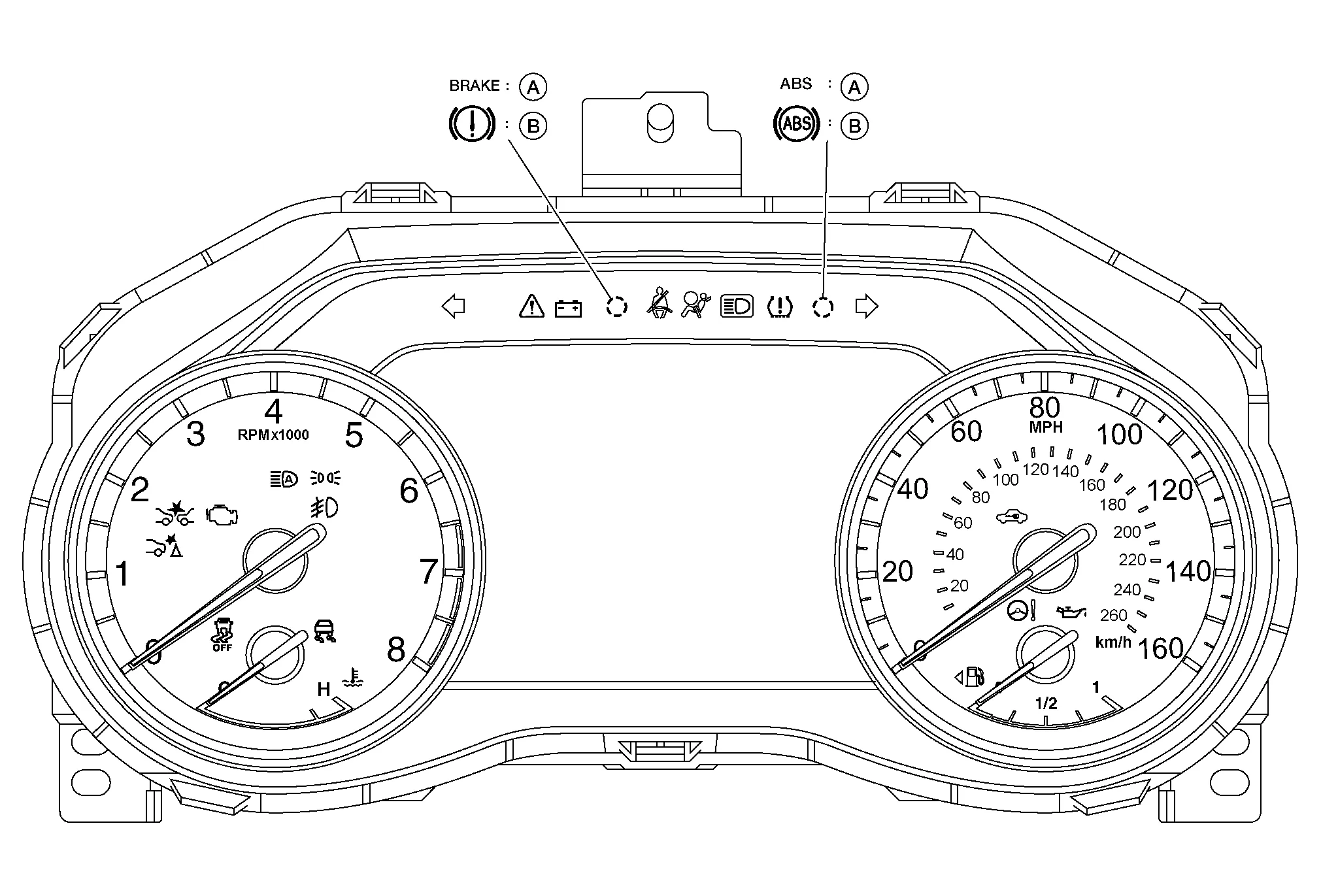
| A: | USA | B: | Except USA |
The combination meter controls the following items according to the signals received from each unit via CAN communication and the signals from switches and sensors:
-
Speedometer
-
Tachometer
-
Engine coolant temperature gauge
-
Fuel gauge
-
Indicator lamps
-
Warning lamps
-
Meter illumination control
-
Meter effect function
-
Information display
-
The steering switches are located on the steering wheel.
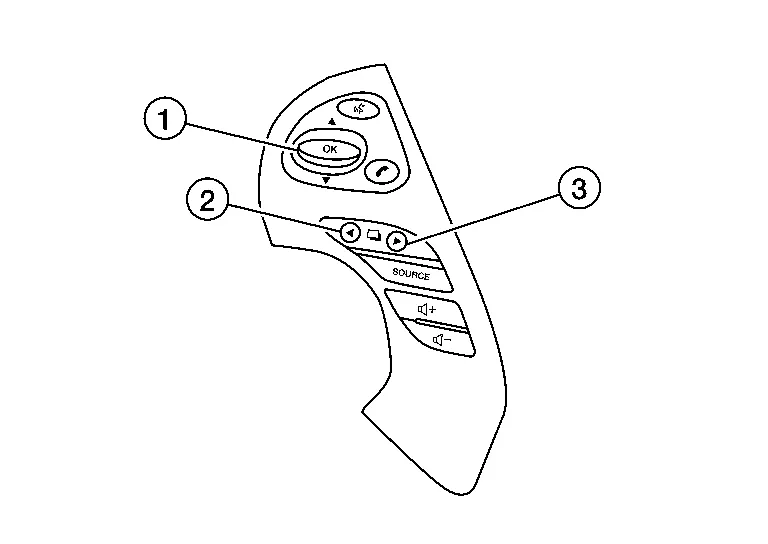
-
The meter system transmits the steering switch signal to the combination meter.
| No. | Switch name | Operation | Description |
|---|---|---|---|
| 1. | Enter/Up/Down switch | Press | The information display settings can be changed. |
| 2. | Back switch | ||
| 3. | Display switch |
-
The meter control switch is located on the instrument lower panel LH.
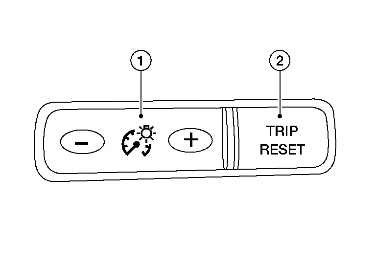
-
The meter control switch transmits the following signals to the combination meter:
-
Trip reset switch signal
-
Illumination control switch signal (+)
-
Illumination control switch signal (−)
-
| No. | Switch name | Operation | Description |
|---|---|---|---|
| 1. | Illumination control switch | Press | An illuminance level of the back light of the combination meter can be adjusted. |
| 2. | Trip reset switch | Press |
|

 System
..
Other information:
Nissan Murano (Z52) 2015-2024 Owners Manual: Emission control system warranty
Your NISSAN vehicle is covered by the following emission warranties: For USA Emission Defects Warranty Emissions Performance Warranty Details of this warranty may be found with other vehicle warranties in your Warranty Information Booklet which comes with your NISSAN vehicle...
Nissan Murano (Z52) 2015-2024 Service Manual: Key Reminder Function
System Description SYSTEM DIAGRAMINPUT SIGNAL AND OUTPUT SIGNAL Signal name Input Output Description Key ID signal Remote keyless entry receiver BCM The BCM receives key ID signal inputs and activates the actuators accordingly. Inside key antenna signal Inside key antenna BCM The BCM receives inside key antenna signals inputs and activates the actuators accordingly...
Categories
- Manuals Home
- Nissan Murano Owners Manual
- Nissan Murano Service Manual
- Checking engine oil level
- Vehicle Dynamic Control (VDC) OFF switch
- Turning the AEB system on/off
- New on site
- Most important about car
Vehicle security system

Your vehicle has two types of security systems:
Vehicle security system NISSAN Vehicle Immobilizer SystemThe vehicle security system provides visual and audible alarm signals if someone opens the doors, liftgate or the hood when the system is armed. It is not, however, a motion detection type system that activates when a vehicle is moved or when a vibration occurs.