Nissan Murano: Brake System :: Removal and Installation / Brake Master Cylinder
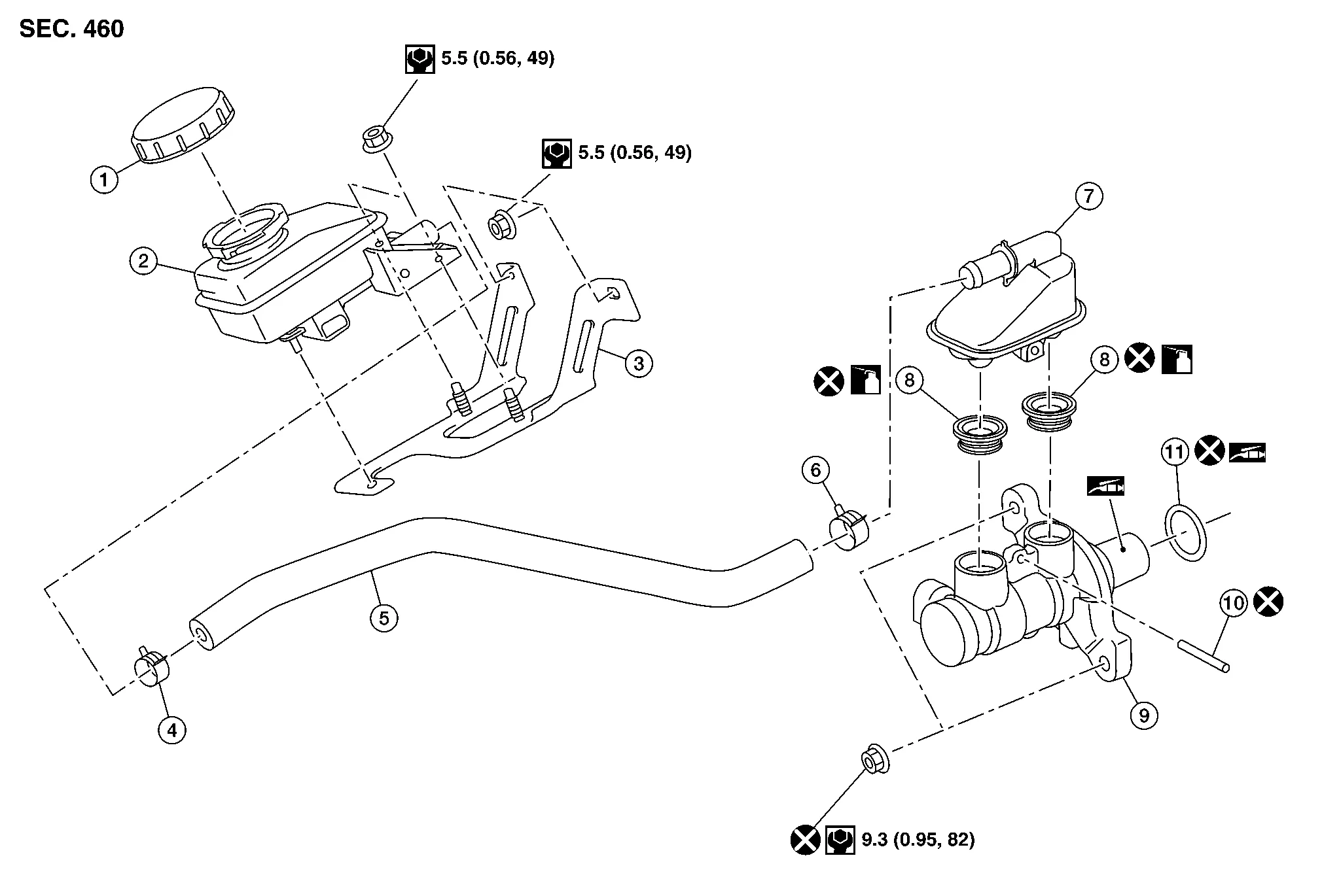
| 1. | Sub tank cap | 2. | Sub tank | 3. | Sub tank bracket |
| 4. | Clamp | 5. | Hose | 6. | Clamp |
| 7. | Reservoir tank | 8. | Grommet | 9. | Cylinder body |
| 10. | Pin | 11. | O-ring | ||
 |
Apply PBC (Poly Butyl Cuprysil) grease or silicone-based grease. | ||||
 |
Apply brake fluid. | ||||
CAUTION:
-
Do not spill or splash brake fluid on painted areas; it may cause paint damage. If brake fluid is splashed on painted areas, wash it away with water immediately.
-
Do not reuse drained brake fluid.
 NOTE:
NOTE:
When removing components such as hoses, tubes/lines, etc., cap or plug openings to prevent fluid from spilling.
REMOVAL
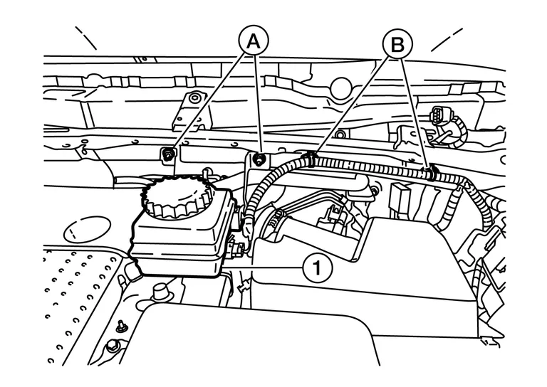
Remove sub tank cap.
Remove the sub tank bracket nuts (A), release the brake fluid level switch harness clips (B) and position the sub tank assembly (1) aside.
Remove air cleaner case as an assembly. Refer to Removal and Installation.
Disconnect the brake pipes from the master cylinder assembly with a flare nut wrench.
CAUTION:
Do not scratch the flare nut or the brake pipe.
Remove the master cylinder assembly.
CAUTION:
Do not depress the brake pedal after the master cylinder assembly is removed.
INSTALLATION
Installation is in the reverse order of removal.
CAUTION:
-
Do not spill or splash brake fluid on painted areas; it may cause paint damage. If brake fluid is splashed on painted areas, wash it away with water immediately.
-
Do not reuse master cylinder assembly nuts.
-
Do not reuse O-ring.
-
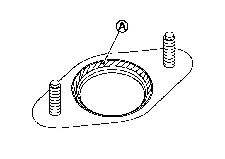
Apply PBC (Poly Butyl Cuprysil) silicone-based grease to the brake booster (A) when installing the master cylinder assembly to the brake booster.
-
Temporarily tighten the brake tube flare nut to the master cylinder assembly by hand. Then tighten it to the specified torque with a flare nut crowfoot and torque wrench. Refer to Exploded View.
CAUTION:
Do not scratch the flare nut or the brake pipe.
-
After installation, perform the air bleeding. Refer to Bleeding Brake System.
DISASSEMBLY
CAUTION:
-
Do not disassemble the cylinder body.
-
Remove the reservoir tank only when necessary.
-
Do not drop removed parts. The parts must not be reused if they are dropped.
Secure the master cylinder assembly in a vise.
CAUTION:
Always use copper plates or cloth between vise and cylinder body. Do not overtighten the vise.
Remove the reservoir tank pin using suitable tools.
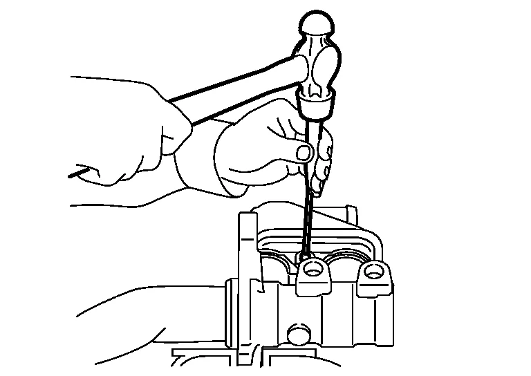
CAUTION:
Do not reuse the pin.
Remove the reservoir tank and grommets from the cylinder body. Discard the grommets.
CAUTION:
-
Do not drop parts. Dropped parts must not be reused.
-
Do not reuse the grommets.
ASSEMBLY
Apply new brake fluid to the grommets and install them to the cylinder body.
CAUTION:
Do not use mineral oil such as gasoline or light oil.
Install the reservoir tank to the cylinder body.
CAUTION:
Do not drop the parts during installation. The parts must not be reused if they are dropped.
Tilt the reservoir tank so that the pin can be inserted. Insert a pin using suitable tools.
CAUTION:
Do not reuse the pin.
 Rear
Rear
Exploded View
1.
Rear brake pipe assembly - RH
2.
Rear brake pipe assembly - LH
3.
Lock plate
4.
Rear brake hose
5.
Union bolt
6...
 Brake Booster
Exploded View
1.
Master cylinder assembly
2.
Vacuum sensor
3.
Brake booster
4.
Lock nut
5.
Clevis
6.
Gasket
Removal and Installation
REMOVALRemove instrument lower panel LH...
Other information:
Nissan Murano (Z52) 2015-2024 Service Manual: L Terminal Circuit (open)
Diagnosis Procedure CHECK "L" TERMINAL CONNECTION Ignition switch OFF. Check if "L" terminal is clean and tight. Is the inspection result normal? YES>> GO TO 2. NO>> Repair "L" terminal connection. Confirm repair by performing system test using 165-DSS-5000P...
Nissan Murano (Z52) 2015-2024 Service Manual: B2098 Ign Relay on Circ
DTC Description IPDM E/R operates the ignition relay-1 when it receives an ignition switch ON signal from BCM via CAN communication. Turn the ignition relay-1 OFF by pressing the push-button ignition switch once when the Nissan Murano vehicle speed is 2...
Categories
- Manuals Home
- Nissan Murano Owners Manual
- Nissan Murano Service Manual
- Settings
- Memory storage function (key-link)
- Checking engine oil level
- New on site
- Most important about car
Fuel gauge

The gauge indicates the approximate fuel level in the tank.
The gauge may move slightly during braking, turning, acceleration, or going up or down hills.
The gauge needle returns to 0 (Empty) after the ignition switch is placed in the OFF position.