Nissan Murano: Brake System :: Removal and Installation / Brake Booster
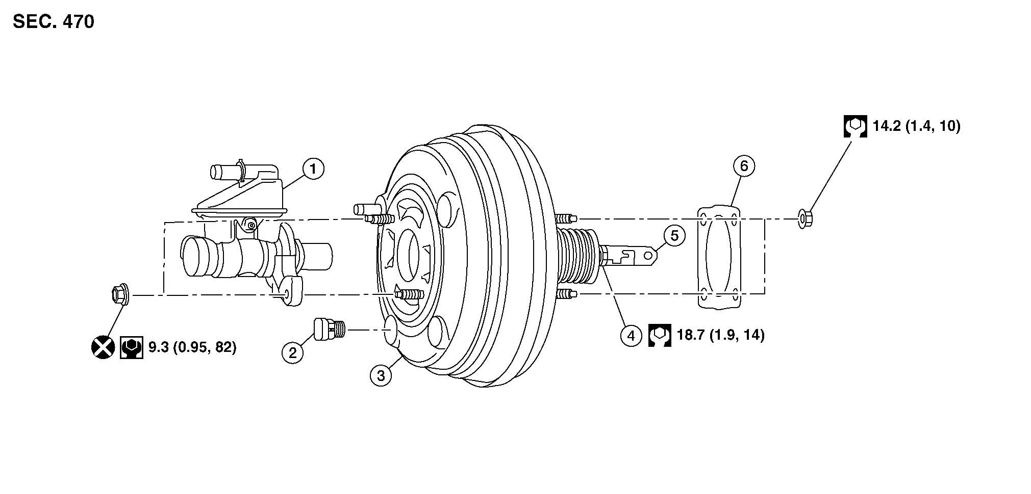
| 1. | Master cylinder assembly | 2. | Vacuum sensor | 3. | Brake booster |
| 4. | Lock nut | 5. | Clevis | 6. | Gasket |
REMOVAL
Remove instrument lower panel LH. Refer to Removal and Installation.
Remove harness clip.
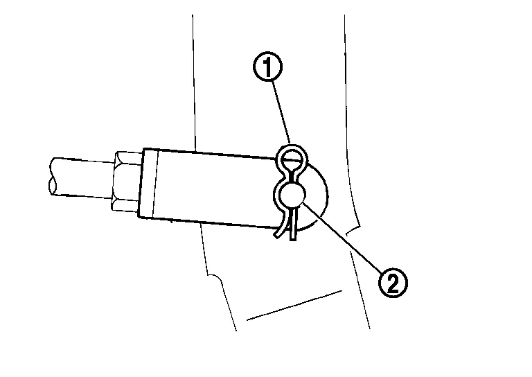
Remove the snap pin (1) and clevis pin (2) from the brake pedal.
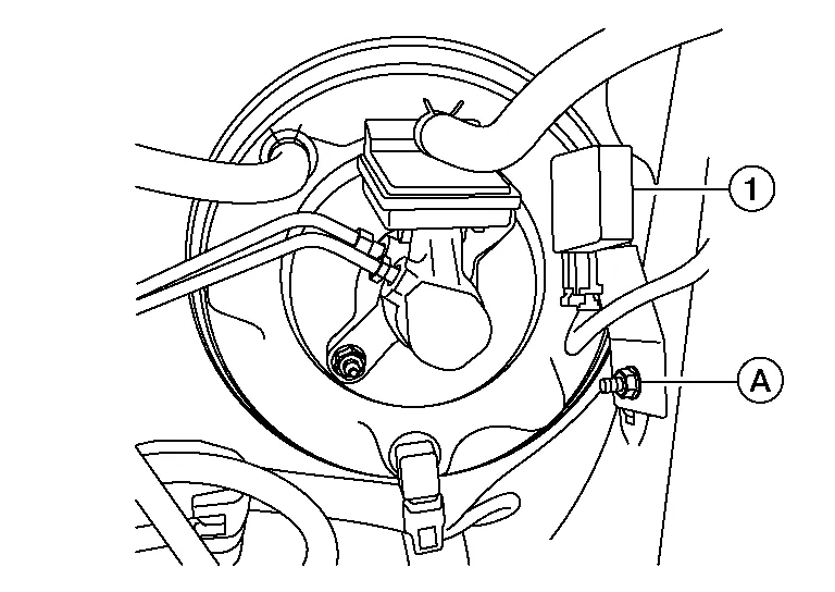
Remove the bolt (A) from the Intelligent Key® warning buzzer (1) from the strut tower and place Intelligent Key® warning buzzer (1) aside.
Remove master cylinder assembly. Refer to Removal and Installation.
Disconnect vacuum hose from brake booster. Refer to Exploded View.
Disconnect the harness connector from the vacuum sensor.
Remove the four nuts on the brake booster.
CAUTION:
Secure the brake booster to avoid damage to components.
Remove the brake booster from the dash panel on the engine room side.
CAUTION:
Do not deform or bend the brake pipes.
INSTALLATION
Loosen lock nut (1) and adjust input rod (2) to the specified length (B).
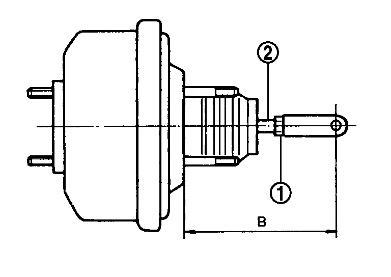
| Length (B) | : Refer to Brake Booster. |
After adjustment, temporarily tighten lock nut to install booster assembly.
Install gasket between the brake booster and dash panel.
Install the brake booster to the dash panel from the engine room side.
CAUTION:
Do not damage brake booster stud bolt threads during installation.
Install the four nuts to the brake booster and brake pedal assembly. Refer to Exploded View.
Connect the harness connector to the vacuum sensor.
Install the Intelligent Key® warning buzzer to the strut tower.
Connect vacuum hose to brake booster. Refer to Exploded View.
Install master cylinder assembly. Refer to Removal and Installation.
Install the cowl top extension. Refer to Removal and Installation - Cowl Top Extension.
Install the clevis pin and snap pin to the brake pedal.
Install the harness clip.
Adjust the brake pedal. Refer to Adjustment.
Install instrument lower panel LH. Refer to Removal and Installation.
Bleed the brake system. Refer to Bleeding Brake System.
Inspect the brake booster. Refer to Inspection.
 Brake Master Cylinder
Exploded View
1.
Sub tank cap
2.
Sub tank
3.
Sub tank bracket
4.
Clamp
5.
Hose
6.
Clamp
7.
Reservoir tank
8.
Grommet
9...
 Vacuum Lines
Exploded View
1.
Clamp
2.
Vacuum hose
3.
Vacuum pipe
4.
Clip
5.
Vacuum hose
6.
Check valve
A.
To intake manifold collector...
Other information:
Nissan Murano (Z52) 2015-2024 Service Manual: Additional Service When Replacing Around View Monitor Control Unit
Description BEFORE REPLACEMENTWhen replacing around view monitor control unit, save or print current vehicle specification with CONSULT configuration before replacement.NOTE: If “Before Replace ECU” cannot be used, use the “After Replace ECU” or “Manual Configuration” after replacing around view monitor control unit...
Nissan Murano (Z52) 2015-2024 Service Manual: C1b0a-16 Power Supply Circuit2
DTC Description DTC DETECTION LOGIC DTC No. CONSULT screen terms (Trouble diagnosis content) DTC detection condition C1B0A-16 POWER SUPPLY CIRCUIT2 (Power supply circuit) Diagnosis condition When ignition switch is ON. Signal (terminal) - Threshold Lane camera unit ignition voltage is less than 10...
Categories
- Manuals Home
- Nissan Murano Owners Manual
- Nissan Murano Service Manual
- GAS STATION INFORMATION
- System malfunction
- Tire rotation
- New on site
- Most important about car
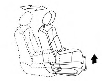
Front manual seat adjustment (if so equipped)
Your vehicle seats can be adjusted manually. For additional information about adjusting the seats, refer to the steps outlined in this section.
Forward and backward