Nissan Murano: Heater & Air Conditioning Control System :: Dtc/circuit Diagnosis / B2632 Dr Air Mix Door Mot
DTC DETECTION LOGIC
| DTC No. |
CONSULT screen terms (Trouble diagnosis content) | DTC detection condition | |
|---|---|---|---|
| B2632 |
DR AIR MIX DOOR MOT (SHORT) (Driver side air mix door motor) |
Diagnosis condition | When ignition switch is ON. |
| Signal (terminal) | - | ||
| Threshold | PBR position 95% or more | ||
| Diagnosis delay time | - | ||
POSSIBLE CAUSE
-
Air mix door motor LH
-
Air mix door motor LH installation condition
-
A/C auto amp.
-
Harness and connector (Air mix door motor LH circuit is open or shorted)
FAIL-SAFE
—
PERFORM DTC CONFIRMATION PROCEDURE
 CONSULT
-
Ignition switch ON.
-
Select “Self Diagnostic Result” mode of “HVAC”.
-
Check DTC.
Is DTC detected?
YES>>Refer to DTC Diagnosis Procedure.
NO>>Inspection End.
CHECK AIR MIX DOOR MOTOR LH COMMUNICATION SIGNAL
-
Ignition switch ON.
-
Check output waveform between air mix door motor LH harness connector and ground with the oscilloscope.
+ − Output waveform Air mix door motor LH Connector Terminal M155 3 Ground 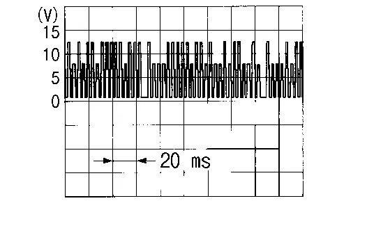
Is the inspection result normal?
YES>>GO TO 2.
NO>>GO TO 3.
CHECK INSTALLATION OF AIR MIX DOOR MOTOR LH
Check air mix door motor LH is properly installed. Refer to Exploded View.
Is the inspection result normal?
YES>>Replace air mix door motor LH. Refer to Removal and Installation - (LH).
NO>>Repair or replace malfunctioning part.
CHECK AIR MIX DOOR MOTOR LH COMMUNICATION SIGNAL CIRCUIT
-
Ignition switch OFF.
-
Disconnect air mix door motor LH connector and A/C auto amp. connector.
-
Check continuity between air mix door motor LH harness connector and A/C auto amp. harness connector.
Air mix door motor LH A/C auto amp. Continuity Connector Terminal Connector Terminal M155 3 M50 16 Yes
Is the inspection result normal?
YES>>Replace A/C auto amp. Refer to Removal and Installation.
NO>>Repair harness or connector.
 B2630 Sunload Sensor
DTC Description
DTC DETECTION LOGIC DTC No.
CONSULT screen terms
(Trouble diagnosis content) DTC detection condition
B2630
SUNLOAD SENSOR (SHORT)
(Sunload sensor)
Diagnosis condition
When ignition switch is ON...
 B2667 Pass Sunload Sensor
DTC Description
DTC DETECTION LOGICNOTE:
If DTC is displayed along with DTC U1000 or U1010, first diagnose the DTC U1000 or U1010. Refer to DTC Description (U1000) or DTC Description (U1010)...
Other information:
Nissan Murano (Z52) 2015-2024 Service Manual: Door Outside Molding
Exploded View 1. Front door panel 2. Front door outside molding 3. Rear door panel 4. Rear door outside molding Pawl Removal and Installation FRONT DOOR OUTSIDE MOLDINGRemovalLower front door glass. Remove door mirror. Refer to Removal and Installation...
Nissan Murano (Z52) 2015-2024 Service Manual: How to Use This Manual. How to Use This Section
Information “CAN” of LAN Section describes information peculiar to a vehicle and inspection procedures. For trouble diagnosis procedure, refer to Trouble Diagnosis Flow Chart of “CAN FUNDAMENTAL”. Abbreviation List Unit name abbreviations in CONSULT CAN diagnosis and in this section are as per the following list...
Categories
- Manuals Home
- Nissan Murano Owners Manual
- Nissan Murano Service Manual
- Intelligent Forward Collision Warning (I-FCW)
- System malfunction
- Warning lights
- New on site
- Most important about car
Seatback pockets

Theremaybe one or two seatback pockets located on the back of the driver and passenger seats. The pockets can be used to store maps.
WARNING