Nissan Murano: Dtc/circuit Diagnosis / B2614 Bcm
DTC DETECTION LOGIC
| DTC No. |
CONSULT screen items (Trouble diagnosis content) | DTC Detection Condition | |
|---|---|---|---|
| B2614 |
BCM (Body control module) |
Diagnosis condition | Always |
| Signal (terminal) | Accessory relay-1 control | ||
| Threshold |
The following states are compared, and they do not match for 1 second or more:
|
||
| Diagnosis delay time | 1 second or more. | ||
POSSIBLE CAUSE
-
Harness or connectors (Accessory relay-1 control signal circuit is open or shorted)
-
BCM
-
Accessory relay-1
FAIL-SAFE
—
PERFORM DTC CONFIRMATION PROCEDURE
 CONSULT
-
Ignition switch ACC, and wait for 1 second or more.
-
Select “Self Diagnostic Result” mode of “BCM”.
-
Check DTC.
Is DTC detected?
YES>>Refer to DTC Diagnosis Procedure.
NO>>To check malfunction symptom before repair: Refer to Intermittent Incident.
NO>>Confirmation after repair: Inspection End.
CHECK ACCESSORY RELAY-1 CONTROL SIGNAL
Check voltage between BCM harness connector and ground.
| (+) | (–) | Condition |
Voltage (Approx.) | ||
|---|---|---|---|---|---|
| BCM | |||||
| Connector | Terminal | ||||
| M80 | 113 | Ground | Ignition switch | OFF | 0 – 0.5 V |
| ACC or ON | Battery voltage | ||||
Is the inspection result normal?
YES>>Replace BCM. Refer to Removal and Installation.
NO>>GO TO 2.
CHECK ACCESSORY RELAY-1 CONTROL SIGNAL CIRCUIT
-
Ignition switch OFF.
-
Disconnect BCM connector and accessory relay-1 connector.
-
Check continuity between BCM harness connector and accessory relay-1 harness connector.
BCM Accessory relay-1 Continuity Connector Terminal Connector Terminal M80 113 J-3 2 Yes -
Check continuity between BCM harness connector and ground.
BCM — Continuity Connector Terminal M80 113 Ground No
Is the inspection result normal?
YES>>GO TO 3.
NO>>Repair or replace harness or connectors.
CHECK ACCESSORY RELAY-1 GROUND CIRCUIT
Check continuity between accessory relay-1 harness connector and ground.
| Accessory relay-1 | — | Continuity | |
| Connector | Terminal | ||
| J-3 | 1 | Ground | Yes |
Is the inspection result normal?
YES>>GO TO 4.
NO>>Repair or replace harness or connectors.
CHECK ACCESSORY RELAY-1
Refer to Component Inspection.
Is the inspection result normal?
YES>>Replace BCM. Refer to Removal and Installation.
NO>>Replace accessory relay-1.
CHECK ACCESSORY RELAY-1
-
Ignition switch OFF.
-
Disconnect accessory relay-1 connector.
-
Check the continuity between accessory relay-1 terminals.
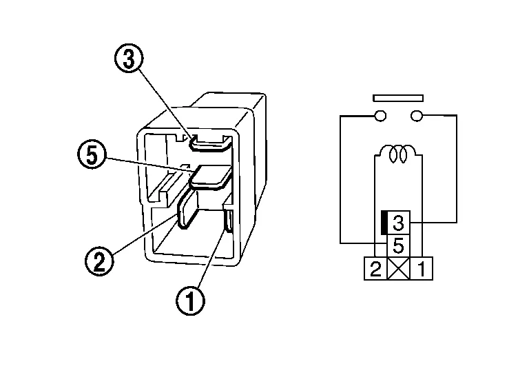
Accessory relay-1 Condition Continuity Terminals 3 5 12 V direct current supply between terminals 1 and 2 Yes No current supply No
Is the inspection result normal?
YES>>Inspection End.
NO>>Replace accessory relay-1.
 B260a Ignition Relay
DTC Description
DTC DETECTION LOGIC DTC No. CONSULT screen terms (Trouble diagnosis content) DTC Detection Condition
B260A
IGNITION RELAY
(Ignition relay)
Diagnosis condition
When ignition switch ON...
 B261a Push-Btn Ign Sw
DTC Description
DTC DETECTION LOGIC DTC No. CONSULT screen terms (Trouble diagnosis content) DTC Detection Condition
B261A
PUSH-BTN IGN SW
(Push-button ignition switch)
Diagnosis condition
When push-button ignition switch is ON...
Other information:
Nissan Murano (Z52) 2015-2024 Service Manual: Configuration
Description Since vehicle specifications are not yet written in a new air bag diagnosis sensor unit, it is necessary to write the specifications to the new unit and then perform “Re/programming, Configuration” with CONSULT. For details, refer to Work Procedure...
Nissan Murano (Z52) 2015-2024 Service Manual: P0532 Refrigerant Pressure Sensor
DTC Description DTC DETECTION LOGIC DTC No. CONSULT screen terms (Trouble diagnosis content) DTC detecting condition P0532 REFRIGERANT PRESS SENSOR A (A/C refrigerant pressure sensor A circuit low) Diagnosis condition Ignition switch ON Engine running Signal (terminal) Refrigerant pressure sensor signal Threshold ECM detects that input signal from the refrigerant pressure sensor is out of the specified range...
Categories
- Manuals Home
- Nissan Murano Owners Manual
- Nissan Murano Service Manual
- Indicator lights
- Memory storage function (key-link)
- System malfunction
- New on site
- Most important about car
Autolight system
The autolight system allows the headlights to turn on and off automatically. The autolight system can:
Turn on the headlights, front parking, tail, license plate and instrument panel lights automatically when it is dark. Turn off all the lights (except daylight running lights) when it is light. Keep all the lights on for a period of time after you place the ignition switch in the OFF position and all doors are closed.