Nissan Murano: Door & Lock :: Dtc/circuit Diagnosis / B2422 Back Door State
DTC DETECTION LOGIC
| DTC No. |
CONSULT screen items (Trouble diagnosis content) | DTC detecting condition | |
|---|---|---|---|
| B2422–78 |
BACK DOOR STATE (Back door state) |
Diagnosis condition | All times |
| Signal (terminal) | Encoder LH A signal, encoder LH B signal, encoder RH A signal, encoder RH B signal (automatic back door control module connector terminal: 19, 20, 21) | ||
| Threshold | When the automatic back door control module detect the encoder pulse signal LH does not according with the encoder pulse signal RH | ||
| Diagnosis delay time | – | ||
| B2422–79 |
BACK DOOR STATE (Back door state) |
Diagnosis condition | All times |
| Signal (terminal) | – | ||
| Threshold | When automatic back door position information is deleted from automatic back door control module memory | ||
| Diagnosis delay time | – | ||
POSSIBLE CAUSE
-
Improper installation of back door assembly
-
Calibration of automatic back door position information
-
Back door mechanism
-
Encoder
-
Harness or connectors (encoder circuit is open or shorted)
-
Automatic back door control module
-
Battery terminal is disconnected and reconnected
FAIL-SAFE
Inhibit automatic back door system auto open/close function
PERFORM DTC CONFIRMATION PROCEDURE
 CONSULT
-
Ignition switch ON.
-
Operate automatic back door.
-
Select “Self Diagnostic Result” mode of “AUTO BACK DOOR”.
Is DTC detected?
YES>>DTC “B2422-78”: Refer to DTC Diagnosis Procedure (B2422-78).
YES>>DTC “B2422-79”: Refer to DTC Diagnosis Procedure (B2422-79).
NO>>To check malfunction symptom before repair: Refer to Intermittent Incident.
NO>>Confirmation after repair: Inspection End.
CHECK INSTALLATION OF BACK DOOR ASSEMBLY
-
Check that back door assembly is installed normally.
Refer to Adjustment.
-
Check back door assembly mechanism deformation, looseness, rattle, interference with other parts, and pinched foreign materials.
Is the inspection result normal?
YES>>GO TO 3.
NO>>GO TO 2.
ADJUST BACK DOOR ASSEMBLY INSTALLATION AND ERASE DTC
CONSULT
-
Ignition switch OFF.
-
Adjust the back door assembly installation. Refer to Adjustment.
-
Ignition switch ON.
-
Select “Self Diagnostic Result” mode of “AUTO BACK DOOR”.
-
Erase DTC, and then repeat “DTC CONFIRMATION PROCEDURE”. Refer to DTC Confirmation Procedure.
Is DTC “B2422-78” detected?
YES>>GO TO 3.
NO>>Inspection End.
CALIBRATION OF AUTOMATIC BACK DOOR POSITION INFORMATION
CONSULT
-
Perform initialization setting of automatic back door position information.
Refer to Work Procedure.
-
Erase DTC, and then repeat “DTC CONFIRMATION PROCEDURE”. Refer to DTC Confirmation Procedure.
Is DTC “B2422-78” detected?
YES>>GO TO 4.
NO>>Inspection End.
CHECK ENCODER MONITOR ITEM
CONSULT
-
Ignition switch ON.
-
Select “SPINDLE LH ENCODER A”, “SPINDLE LH ENCODER B”, “SPINDLE RH ENCODER A” and “SPINDLE RH ENCODER B” in “Data Monitor” mode of “AUTO BACK DOOR”.
-
Check that the function operates normally according to the following conditions:
Monitor item Condition Status SPINDLE LH ENCODER A Back door Moving (auto or manual) HI ⇔ LO When stopped HI or LO SPINDLE LH ENCODER B Moving (auto or manual) HI ⇔ LO When stopped HI or LO SPINDLE RH ENCODER A Back door Moving (auto or manual) HI ⇔ LO When stopped HI or LO SPINDLE RH ENCODER B Moving (auto or manual) HI ⇔ LO When stopped HI or LO
Is the inspection result normal?
YES>>GO TO 11.
NO>>GO TO 5.
CHECK ENCODER POWER SUPPLY
-
Ignition switch OFF.
-
Disconnect spindle unit connector.
-
Check voltage between spindle unit harness connector and ground.
(+) (–) Voltage
(Approx.)Spindle unit Connector Terminal LH B70 6 Ground Battery voltage RH B162
Is the inspection result normal?
YES>>GO TO 7.
NO>>GO TO 6.
CHECK ENCODER POWER SUPPLY CIRCUIT
-
Disconnect automatic back door control module connector.
-
Check continuity between automatic back door control module harness connector and spindle unit harness connector.
Automatic back door control module Spindle unit Continuity Connector Terminal Connector Terminal B55 19 LH B70 6 Yes 20 RH B162 -
Check continuity between automatic back door control module harness connector and ground.
Automatic back door control module Ground Continuity Connector Terminal B55 19 No 20
Is the inspection result normal?
YES>>Replace automatic back door control module. Refer to Removal and Installation.
NO>>Repair or replace harness.
CHECK ENCODER CIRCUIT GROUND CIRCUIT
-
Disconnect automatic back door control module connector.
-
Check continuity between automatic back door control module harness connector and spindle unit harness connector.
Automatic back door control module Spindle unit Continuity Connector Terminal Connector Terminal B55 21 LH B70 3 Yes RH B162 -
Check continuity between automatic back door control module harness connector and ground.
Automatic back door control module Ground Continuity Connector Terminal B55 21 No
Is the inspection result normal?
YES>>GO TO 8.
NO>>Repair or replace harness.
CHECK ENCODER OUTPUT SIGNAL
-
Connect spindle unit and automatic back door control module connector.
-
Check signal between spindle unit harness connector and ground using oscilloscope.
(+) (–) Condition Voltage
(Approx.)Spindle unit Connector Terminal LH B70 7 Ground Back door Moving (auto) 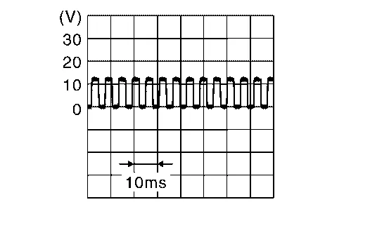
When stopped 0 V or 12 V 10 Moving (auto) When stopped 0 V or 12 V RH B162 7 Moving (auto) When stopped 0 V or 12 V 10 Moving (auto) When stopped 0 V or 12 V
Is the inspection result normal?
YES>>GO TO 10.
NO>>GO TO 9.
CHECK ENCODER OUTPUT SIGNAL CIRCUIT
-
Disconnect automatic back door control module and spindle unit connector.
-
Check continuity between automatic back door control module harness connector and spindle unit harness connector.
Spindle unit Automatic back door control module Continuity Connector Terminal Connector Terminal LH B70 7 B55 6 Yes 10 7 RH B162 7 8 10 9 -
Check continuity between automatic back door control module harness connector and ground.
Automatic back door control module Ground Continuity Connector Terminal B55 6 No 7 8 9
Is the inspection result normal?
YES>>Replace automatic back door control module. Refer to Removal and Installation.
NO>>Repair or replace harness.
REPLACE SPINDLE UNIT AND ERASE DTC
CONSULT
-
Ignition switch OFF.
-
Replace spindle unit.
-
Ignition switch ON.
-
Select “Self Diagnostic Result” mode of “AUTO BACK DOOR”.
-
Erase DTC, and then repeat “DTC CONFIRMATION PROCEDURE”. Refer to DTC Confirmation Procedure.
Is DTC “B2422-78” detected?
YES>>Replace automatic back door control module. Refer to Removal and Installation.
NO>>Inspection End.
CHECK INSTALLATION OF SPINDLE UNIT
Check that spindle unit is installed normally. Refer to Removal and Installation.
Is the inspection result normal?
YES>>GO TO 13.
NO>>GO TO 12.
ADJUST SPINDLE UNIT INSTALLATION AND ERASE DTC
CONSULT
-
Ignition switch OFF.
-
Adjust the spindle unit installation.
-
Ignition switch ON.
-
Select “Self Diagnostic Result” mode of “AUTO BACK DOOR”.
-
Erase DTC, and then repeat “DTC CONFIRMATION PROCEDURE”. Refer to DTC Confirmation Procedure.
Is DTC “B2422-78” detected?
YES>>GO TO 13.
NO>>Inspection End.
REPLACE SPINDLE UNIT AND ERASE DTC
CONSULT
-
Ignition switch OFF.
-
Replace spindle unit.
-
Ignition switch ON.
-
Select “Self Diagnostic Result” mode of “AUTO BACK DOOR”.
-
Erase DTC, and then repeat “DTC CONFIRMATION PROCEDURE”. Refer to DTC Confirmation Procedure.
Is DTC “B2422-78” detected?
YES>>Replace automatic back door control module. Refer to Removal and Installation.
NO>>Inspection End.
ERASE DTC
CONSULT
-
Fully close then back door manually.
-
Ignition switch ON.
-
Select “Self Diagnostic Result” mode of “AUTO BACK DOOR”.
-
Erase DTC, and then repeat “PERFORM DTC CONFIRMATION PROCEDURE”. Refer to DTC Confirmation Procedure.
Is DTC “B2422-79” detected?
YES>>GO TO 2.
NO>>Inspection End.
CHECK AUTOMATIC BACK DOOR CONTROL MODULE EACH DTC
If DTC “B2422-79” is displayed with DTC “B2426-23, B2426-24, B2426-29, B2427-23, B2427-24, B2427-29”, first perform the trouble diagnosis for DTC “B2426-23, B2426-24, B2426-29, B2427-23, B2427-24, B2427-29”.
Is DTC “B2426-23, B2426-24, B2426-29, B2427-23, B2427-24, B2427-29” detected?
YES>>Refer to DTC Index.
NO>>Replace automatic back door control module. Refer to Removal and Installation.
 B2416 Touch Sen R Open
DTC Description
DTC DETECTION LOGIC DTC No.
CONSULT screen items
(Trouble diagnosis content) DTC detecting condition
B2416–1B
TOUCH SEN R OPEN
(Touch sensor right open)
Diagnosis condition
All times
Signal (terminal)
Touch sensor RH signal (automatic back door control module connector terminal: 4)
Threshold
When one of the following conditions is satisfied
Touch sensor RH circuit is open
Disconnect touch sensor RH connector
Diagnosis delay time
–
B2416–1E
TOUCH SEN R OPEN
(Touch sensor right open)
Diagnosis condition
All times
Signal (terminal)
Touch sensor RH signal (automatic back door control module connector terminal: 4)
Threshold
When one of the following conditions is satisfied
Touch sensor RH circuit is open
Disconnect touch sensor RH connector
Diagnosis delay time
–
POSSIBLE CAUSE
Improper installation of touch sensor
Touch sensor RH
Harness or connectors (touch sensor circuit is open)
Automatic back door control module
FAIL-SAFEInhibit automatic back door system auto open/close function
DTC Confirmation Procedure
PERFORM DTC CONFIRMATION PROCEDURE
CONSULT
Ignition switch ON...
 B2423 Abd Mtr Time Out
DTC Description
DTC DETECTION LOGIC DTC No.
CONSULT screen items
(Trouble diagnosis content) DTC detecting condition
B2423
ABD MTR TIME OUT
(Automatic back door motor time out)
Diagnosis condition
When the automatic back door is operated approximately 5-6 times (open & close cycles) continuously (for 60–100 seconds in any direction) without any stoppages, the control module will momentarily inhibit operation to protect the system...
Other information:
Nissan Murano (Z52) 2015-2024 Service Manual: P0712 Transmission Fluid Temperature Sensor a
DTC Description DTC DETECTION LOGIC DTC CONSULT screen terms (Trouble diagnosis content) DTC detection condition P0712 FLUID TEMP SENSOR A (Transmission Fluid Temperature Sensor A Circuit Low) Diagnosis condition TCM power supply voltage: More than 11 V Signal CVT fluid temperature sensor signal Threshold Fluid temperature sensor detection voltage: 0...
Nissan Murano (Z52) 2015-2024 Owners Manual: Readiness for Inspection/Maintenance (I/M) test
WARNING A vehicle equipped with All -Wheel Drive (AWD) should never be tested using a two wheel dynamometer (such as the dynamometers used bysomestates for emissions testing), or similar equipment. Make sure you inform the test facility personnel that your vehicle is equipped with AWD before it is placed on a dynamometer...
Categories
- Manuals Home
- Nissan Murano Owners Manual
- Nissan Murano Service Manual
- Checking engine oil level
- Jacking up vehicle and removing the damaged tire
- Intelligent Forward Collision Warning (I-FCW)
- New on site
- Most important about car
LATCH (Lower Anchors and Tethers for CHildren) system

LATCH system lower anchor locations - bench seat
Your vehicle is equipped with special anchor points that are used with LATCH system compatible child restraints. This system may also be referred to as the ISOFIX or ISOFIX compatible system. With this system, you do not have to use a vehicle seat belt to secure the child restraint unless the combined weight of the child and child restraint exceeds 65 lbs. (29.5 kg). If the combined weight of the child and child restraint is greater than 65 lbs. (29.5 kg), use the vehicle’s seat belt (not the lower anchors) to install the child restraint. Be sure to follow the child restraint manufacturer’s instructions for installation.