Nissan Murano: Component Parts / Automatic Back Door System
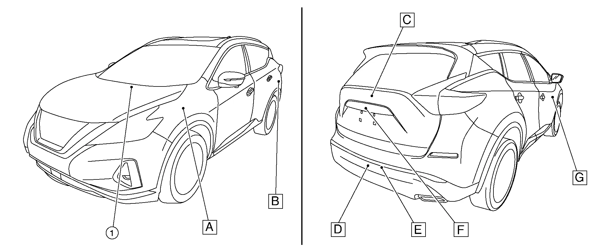

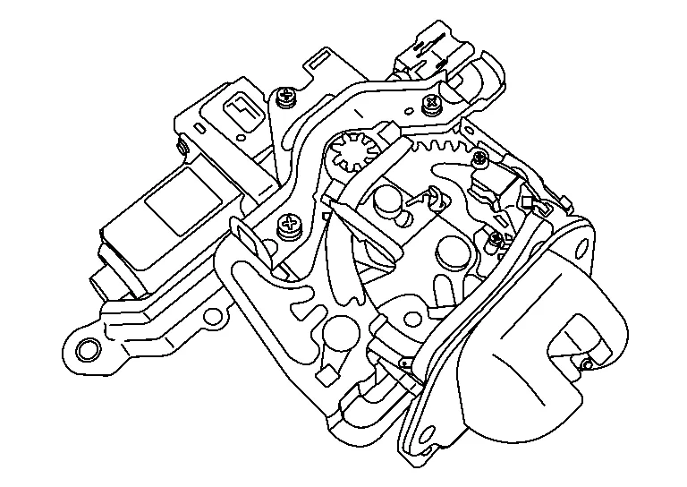
| A. | View of LH side of instrument panel | B. | View with luggage side lower finisher removed | C. | View of back door open |
| D. | View with kick sensor assembly removed from rear fascia | E. | View with rear fascia removed | F. | View of back door |
| No. | Component | Function |
|---|---|---|
| 1. |
BCM (Body Control Module) |
BCM transmits and receives signal to the automatic back door control module. Refer to Component Parts Location for detailed component location. |
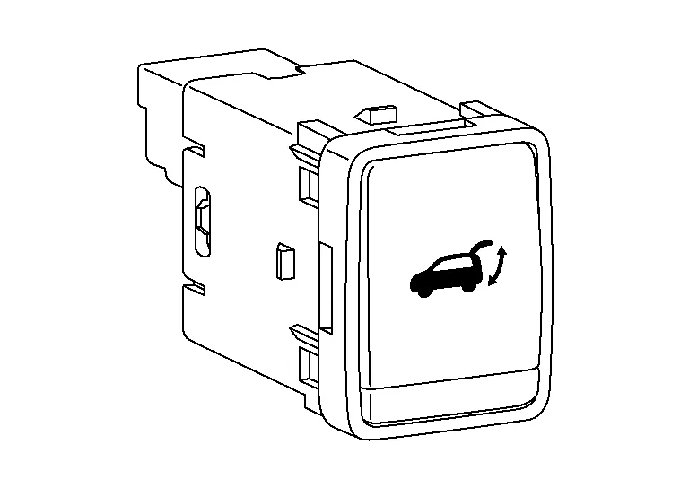
| 2. | Automatic back door switch | Refer to Automatic Back Door Switch. |
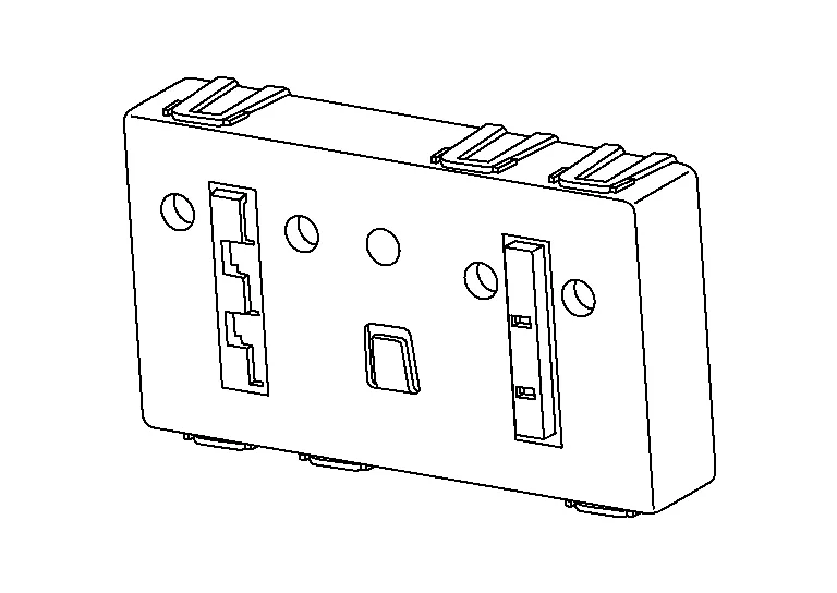
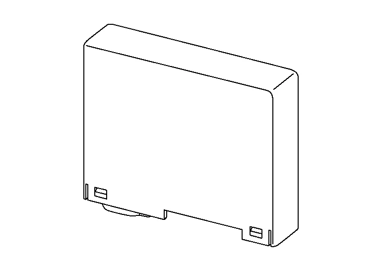
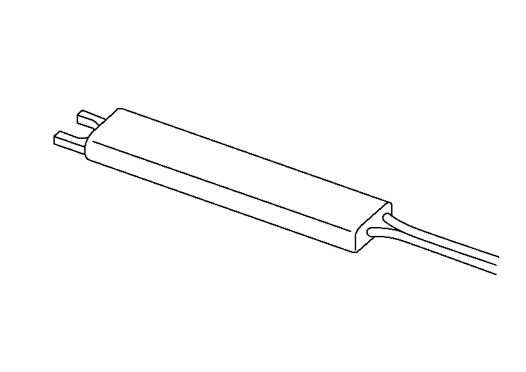
| 3. | Automatic back door control module | Refer to Automatic Back Door Control Module. |
| 4. | Automatic back door close switch | Refer to Automatic Back Door Close Switch. |
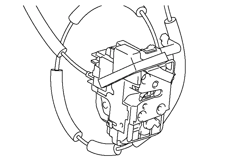
| 5. | Back door lock assembly | Refer to Back Door Lock Assembly. |
| 6. | Touch sensor LH | Refer to Back Door Touch Sensor. |
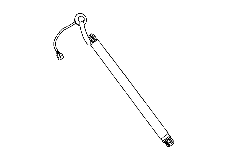
| 7. | Spindle unit LH | Refer to Spindle Unit. |
| 8. | Touch sensor RH | Refer to Back Door Touch Sensor. |
| 9. | Spindle unit RH | Refer to Spindle Unit. |
| 10. | Motion activated back door sensor (upper) | Refer to Motion Activated Back Door Sensors. |
| 11. | Motion activated back door control unit | Refer to Motion Activated Back Door Control Unit. |
| 12. | Motion activated back door sensor (lower) | Refer to Motion Activated Back Door Sensors. |
| 13. | Automatic back door warning buzzer | Refer to Automatic Back Door Warning Buzzer. |
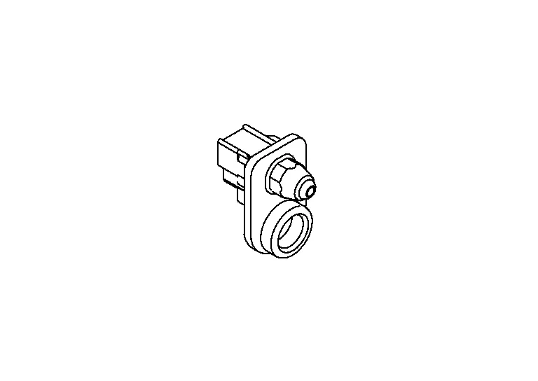
| 14. | Back door opener switch | Refer to Back Door Opener Switch. |
Controls the automatic back door system.
Detects open/close operation of automatic back door.
Warns the user of the automatic back door condition and inappropriate operations with the buzzer sounds.
-
Detects close operation of automatic back door.
-
Transmits automatic back door close switch signal to automatic back door control module.
Back door closure motor, half latch switch, open switch, close switch and back door switch are installed.
-
Closure motor: Inputs open/close signal from automatic back door control module and activates the back door auto closure operation.
-
Half latch switch: Starts the closure motor close operation.
-
Open switch: Stops the closure motor open operation.
-
Close switch: Stops the closure motor close operation.
-
Back door switch: Inputs back door open/close condition to BCM.
-
Detects open operation of automatic back door.
-
Transmits automatic back door opener switch signal to automatic back door control module.
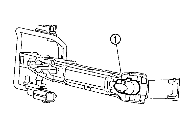
Opener Switch
-
Opener switch (1) transmits back door opener switch signal to BCM.
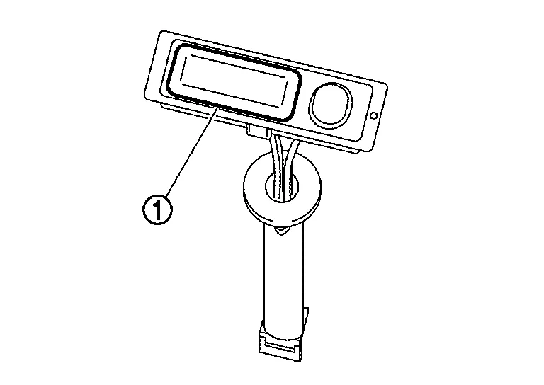
-
Opener switch (1) is integrated into the back door opener switch.
Request Switch
-
Request switch (1) transmits back door request switch signal to BCM.
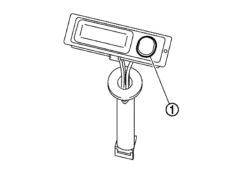
-
Request switch (1) is integrated into the back door opener switch.
During back door close operation, the touch sensor detects any trapped foreign material.
-
Door lock and unlock switch transmits door lock/unlock signal operation to BCM.
-
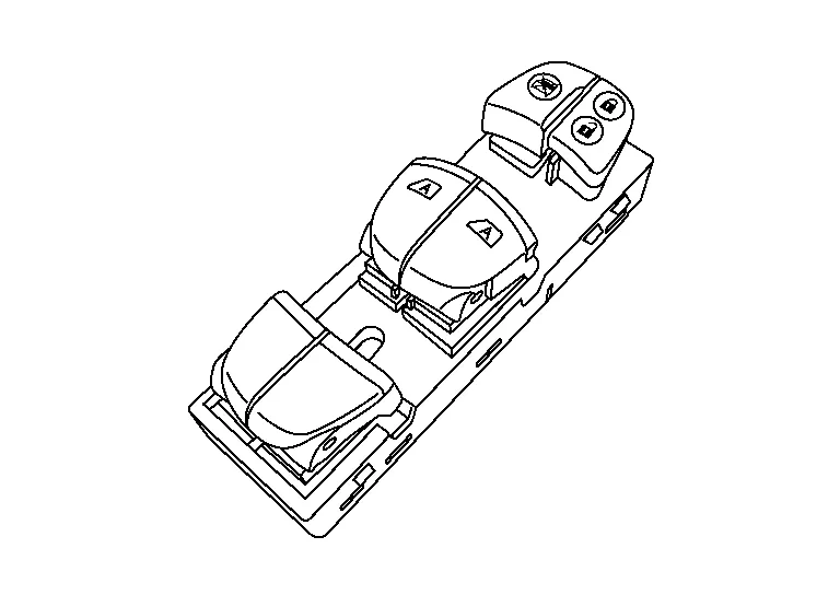
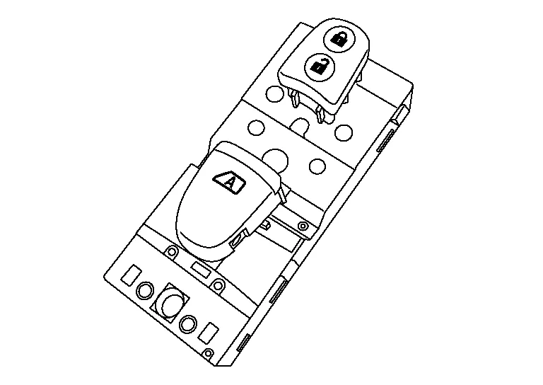
Door lock and unlock switch is integrated into the main power window and door lock/unlock switch.
-
Door lock and unlock switch transmits door lock/unlock signal operation to BCM.
-
Door lock and unlock switch is integrated into the power window and door lock/unlock switch RH.
-
Remote keyless entry receiver receives button operation signal and key ID signal of Intelligent Key and then transmits them to BCM.
-
Remote keyless entry receiver is installed behind the glove box.
-
Inside key antenna (console) detects that Intelligent Key is within the inside detection area and then transmits detection status to BCM.
-
Inside key antenna (luggage room) detects that Intelligent Key is within the inside detection area and then transmits detection status to BCM.
-
Outside key antenna (rear bumper) detects that Intelligent Key is within the outside detection area and then transmits detection status to BCM. Request signal is transmitted simultaneously to Intelligent Key.
-
Outside key antenna (rear bumper) is installed in the rear of rear bumper.
-
Outside key antenna (LH) detects that Intelligent Key is within the outside detection area and then transmits detection status to BCM. Request signal is transmitted simultaneously to Intelligent Key.
-
Outside key antenna (LH) is installed in the front outside handle assembly LH.
-
Outside key antenna (RH) detects that Intelligent Key is within the outside detection area and then transmits detection status to BCM. Request signal is transmitted simultaneously to Intelligent Key.
-
Outside key antenna (RH) is installed in the front outside handle assembly RH.
-
Intelligent Key warning buzzer warns the user, who is outside the vehicle, of operation confirmation according to Intelligent Key operation and door request switch operation or of an inappropriate operation.
-
Intelligent Key warning buzzer is installed in the left side of engine compartment.
-
Front door request switch (LH) transmits door request switch signal to BCM.
-
Front door request switch (LH) (1) is integrated into the front outside handle assembly LH.
-
Front door request switch (RH) transmits door request switch signal to BCM.
-
Front door request switch (RH) (1) is integrated into the front outside handle assembly RH.
Door switch detects open/close status of door and transmits door switch signal to BCM.
Door switch detects open/close status of door and transmits door switch signal to BCM.
-
Door lock actuator and unlock sensor are integrated into driver door lock assembly.
-
Door lock actuator receives lock/unlock signal from BCM and then locks/unlocks driver door.
-
Only front door lock assembly LH integrates unlock sensor. Unlock sensor transmits lock/unlock status of driver seat to BCM.
-
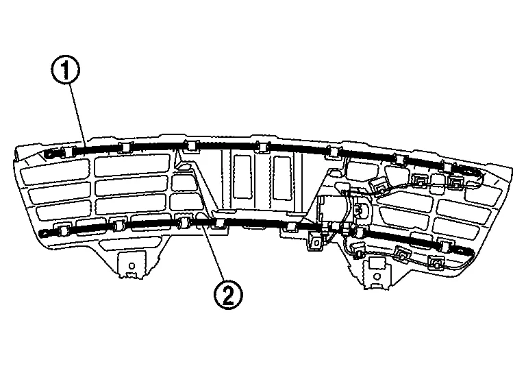
Motion activated back door sensor (upper) (1) and motion activated back door sensor (lower) (2) are installed in the rear fascia.
-
When the user performs a kick motion toward rear bumper while carrying Intelligent Key as shown in the figure, motion activated back door sensor (upper) detects shin motion of leg and motion activated back door sensor (lower) detects instep motion of foot. This varies the voltage waveform of motion activated back door sensor. Motion activated back door sensor control unit judges user operation by detecting the voltage change of motion activated back door sensors.

 NOTE:
NOTE:
Voltage generated in communication circuit between motion activated back door sensor and motion activated back door sensor control unit is extremely low and therefore cannot be measured.
-
It is necessary to perform a kick motion within space as shown in the figure for activating the motion activated back door sensors completely. The detection area may differ depending on the conditions of the surroundings.


-
Intelligent Key must be carried for starting the operation of the automatic back door open/close function by motion activated back door sensor operation (hands free function) with the back door stopped. Intelligent Key does not need to be carried when stopping the back door operation during automatic back door open/close operation (automatic open/close temporary stop function).
-
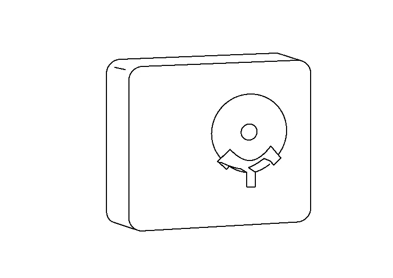
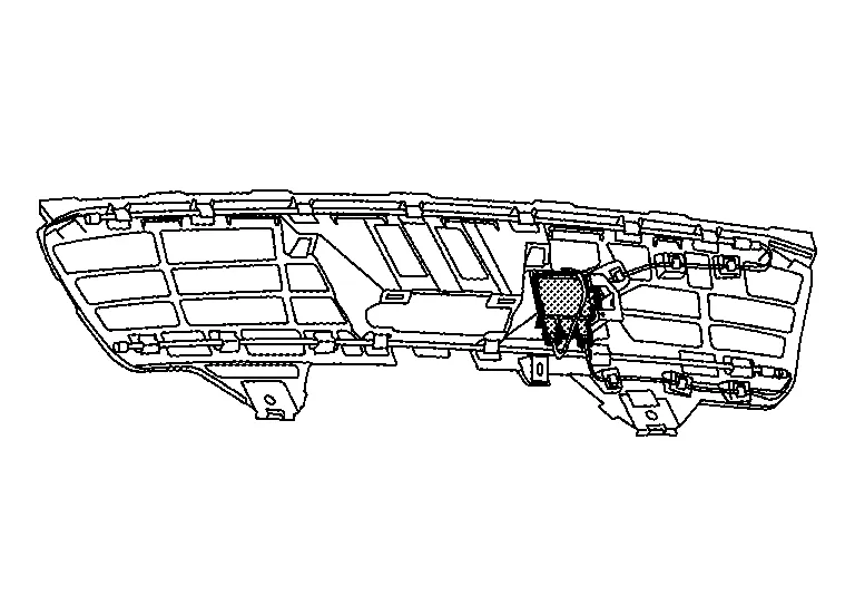
Motion activated back door control unit is installed in the rear fascia.
-
Motion activated back door control unit judges user operation by detecting the voltage waveform change of motion activated back door sensor (upper) and motion activated back door sensor (lower). The motion activated back door control unit then transmits the automatic back door operation request signal to BCM via serial communication.
Encoder and spindle motor are installed:
-
Encoder: Automatic back door control module receives the pulse signals from encoders A and B that occurred due to synchronization with the back door operation. The automatic back door control module calculates the back door position, operation direction, and operation speed according to the received pulse signals.
-
Spindle motor: Inputs open/close signal from automatic back door control module and activates the automatic back door open/close operation.
Within the Homelink® transceiver, a maximum of 3 radio signals can be stored and transmitted to operate the garage door, etc.

 System (power Door Lock System)
System Description
SYSTEM DIAGRAMINPUT SIGNAL AND OUTPUT SIGNAL Signal name Input Output Description
Door lock/unlock switch signal
Door lock/unlock switch
BCM
The BCM receives door lock/unlock switch signals inputs and activates the actuators accordingly...
Other information:
Nissan Murano (Z52) 2015-2024 Service Manual: Steering Column
Exploded View Electric steering column 1. Steering column 2. Hole cover 3. Lower boot 4. Steering intermediate shaft Mechanical steering column 1. Steering column 2. Hole cover 3. Lower boot 4. Steering intermediate shaft Removal and Installation CAUTION: Do not cause impact to steering column during removal and installation...
Nissan Murano (Z52) 2015-2024 Owners Manual: Warning and indicator lights
..
Categories
- Manuals Home
- Nissan Murano Owners Manual
- Nissan Murano Service Manual
- All-Wheel Drive (AWD) (if so equipped)
- Settings
- Memory storage function (key-link)
- New on site
- Most important about car
Vehicle security system

Your vehicle has two types of security systems:
Vehicle security system NISSAN Vehicle Immobilizer SystemThe vehicle security system provides visual and audible alarm signals if someone opens the doors, liftgate or the hood when the system is armed. It is not, however, a motion detection type system that activates when a vehicle is moved or when a vibration occurs.