
Nissan Murano: Steering System :: System Description / Component Parts. Heated Steering Wheel System
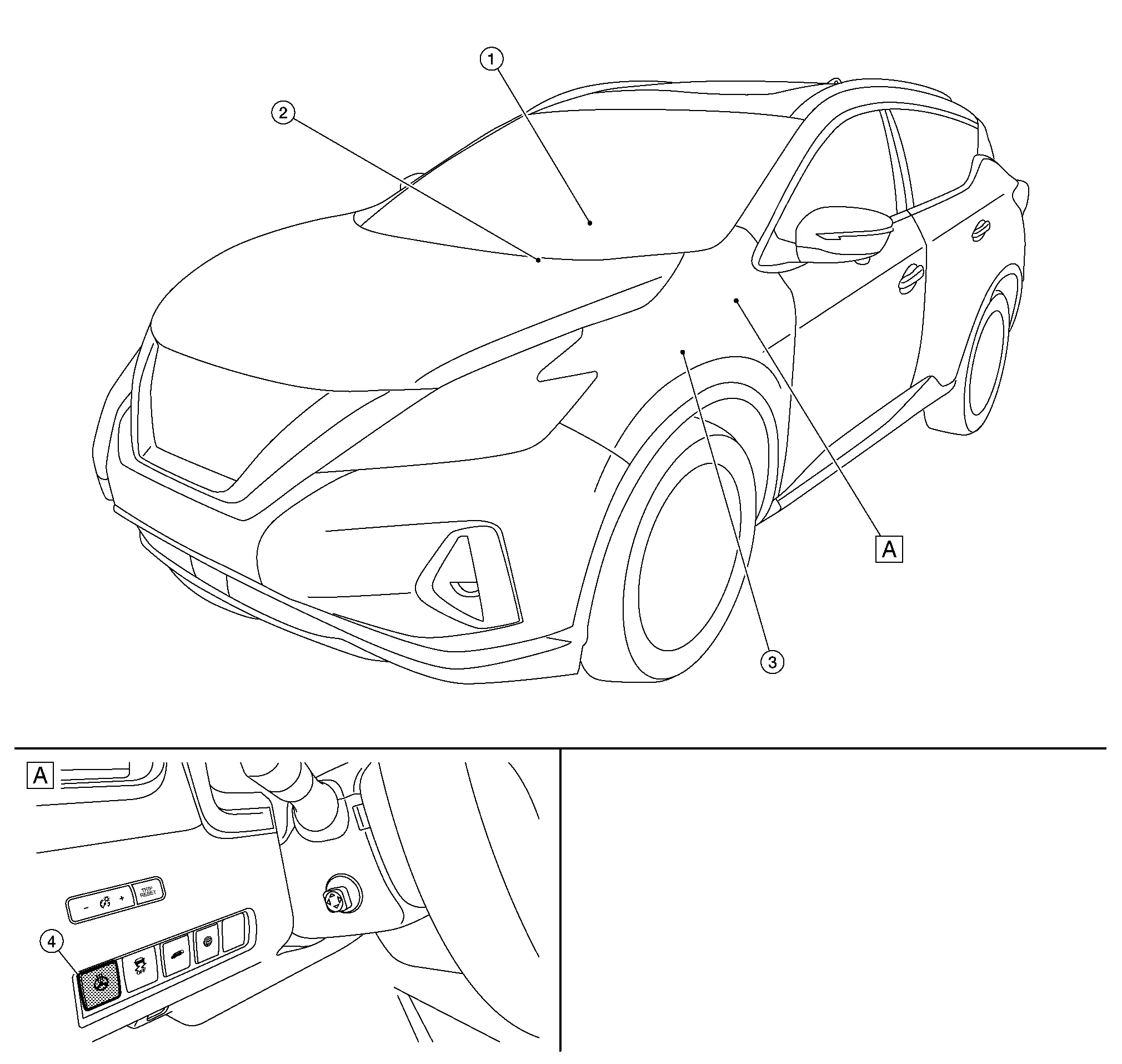
| A. | Left of the steering column |
| No. | Component | Function |
|---|---|---|
| 1. | Heated steering wheel | Refer to Heated Steering Wheel. |
| 2. | A/C auto amp. | Refer to A/C Auto Amp.. |
| 3. | Heated steering wheel relay | Refer to Heated Steering Wheel Relay. |
| 4. | Heated steering wheel switch | Steering heater function ON/OFF. |
With the power supply from the heated steering wheel relay, the heated steering wheel controls temperature through the heating element  and thermostat
  built into the steering wheel.

-
Heating element: Generates heat by energization.
 NOTE:
NOTE:
Heating element is located at the back of the steering wheel leather surface.
-
Thermostat: Turns ON/OFF power supply according to the specified temperature.
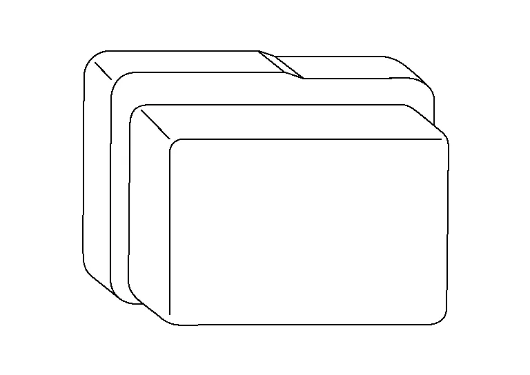
Through the control of the A/C auto amp., the heated steering wheel relay turns ON/OFF electricity to the heating element built into the steering wheel. For location, refer to Component Parts Location.
-
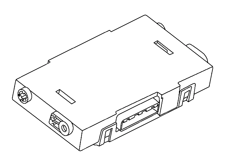
A/C auto amp. is installed behind center of the instrument panel.
-
A/C auto amp. turns ON/OFF the heated steering wheel relay according to a signal transmitted from display control unit via CAN communication.
-
The A/C auto amp. includes a timer. The heated steering wheel relay is turned OFF when the timer operating time reaches 30 minutes.
-
Timer: Turns ON/OFF the heated steering wheel relay for a specified period of time.
-
-
For other information about the A/C auto amp., refer to A/C Auto Amp..

 System. Heated Steering Wheel System
System Description
SYSTEM DIAGRAMINPUT/OUTPUT SIGNAL CHART Switch Input signal to A/C auto amp. A/C auto amp. function Actuator
Heated steering wheel switch
Switch ground signal
Heated steering wheel control
Heated steering wheel
System DescriptionThe heated steering wheel switch controls the heated steering wheel relay through the A/C auto amp...
Other information:
Nissan Murano (Z52) 2015-2024 Service Manual: Hood Switch
Component Function Check CHECK FUNCTION CONSULT Select “HOOD SW” and "HOOD SW 2" in “Data Monitor” mode of “IPDM E/R”. Check “HOOD SW” and "HOOD SW 2" indication under the following conditions: Monitor item Condition Indication HOOD SW Hood Open OFF Close ON HOOD SW 2 Open ON Close OFF Is the indication normal? YES>> Hood switch is OK...
Nissan Murano (Z52) 2015-2024 Service Manual: Cooling System
Cooling Circuit 1. Cylinder block (bank 1) 2. Oil cooler 3. Cylinder head (bank 1) 4. Water pump 5. Radiator 6. Water outlet 7. Thermostat 8. Cylinder head (bank 2) 9. Cylinder block (bank 2) A. To heater. Refer to Exploded View...
Categories
- Manuals Home
- Nissan Murano Owners Manual
- Nissan Murano Service Manual
- GAS STATION INFORMATION
- Checking engine oil level
- Indicator lights
- New on site
- Most important about car
