Nissan Murano: Front Suspension :: Periodic Maintenance / Wheel Alignment
PRELIMINARY INSPECTION
WARNING:
Always adjust wheel alignment with vehicle on a flat surface.
 NOTE:
NOTE:
If wheel alignment is out of specification, inspect and replace any damaged or worn suspension parts before making any adjustments.
Check the following:
-
Check and adjust wheel alignment with vehicle under unladen conditions. “Unladen conditions” means that fuel, engine coolant, and lubricants are full; spare tire, jack, hand tools and mats are in designated positions.
-
Check tires for incorrect air pressure and excessive wear. Refer to Tire Air Pressure.
-
Check wheels for deformation, cracks, and other damage. Remove wheel and check wheel runout. Refer to Inspection.
-
Check wheel bearing axial end play. Refer to Inspection.
-
Check struts for leaks or damage.
-
Check each mounting point of suspension components for any excessive looseness or damage.
-
Check each link, arm, and suspension member for any damage.
-
Check wheelarch height in unladen conditions. Refer to Wheelarch Height (Unladen*).
GENERAL INFORMATION AND RECOMMENDATIONS
A four-wheel thrust alignment should be performed.
-
This type of alignment is recommended for any NISSAN/INFINITI Nissan Murano vehicle.
-
The four-wheel “thrust” process helps ensure that the vehicle is properly aligned and the steering wheel is centered.
-
The alignment machine itself should be capable of accepting any NISSAN/INFINITI Nissan Murano vehicle.
-
The alignment machine should be checked to ensure that it is level.
Make sure the machine is properly calibrated.
-
Your alignment equipment should be regularly calibrated in order to give correct information.
-
Check with the manufacturer of your specific alignment machine for their recommended Service/Calibration Schedule.
ALIGNMENT PROCESS
IMPORTANT:
Use only the alignment specifications listed in this Service Manual. Refer to Wheel Alignment (Unladen1).
When displaying the alignment settings, many alignment machines use “indicators” : (Green/red, plus or minus, Go/No Go.) Do not use these indicators.
-
The alignment specifications programmed into your alignment machine that operate these indicators may not be correct.
-
This may result in an ERROR.
Most camera-type alignment machines are equipped with both a “Rolling Compensation” method and an optional “Jacking Compensation” method to compensate the alignment targets or head units. “Rolling Compensation” is the preferred method.
-
If using the “Rolling Compensation” method, after installing the alignment targets or head units, push or pull on the rear wheel to move the Nissan Murano vehicle. Do not push or pull on the vehicle body.
-
If using the “Jacking Compensation” method, after installing the alignment targets or head units, raise the Nissan Murano vehicle and rotate the wheels 1/2 turn both ways.
NOTE:
Do not use the “Rolling Compensation” method if you are using sensor-type alignment equipment.
-
Follow all instructions for the alignment machine you are using for more information.
CAMBER, CASTER AND KINGPIN INCLINATION ANGLES INSPECTION
CAUTION:
Camber, caster, kingpin inclination angles cannot be adjusted.
Before inspection, set the front wheels onto a turning radius gauge. Set the rear wheels onto a pad that has the same height so the Nissan Murano vehicle will remain horizontal.
TOTAL TOE-IN INSPECTION
Measure the total toe-in using the following procedure:
WARNING:
-
Always perform the following procedure on a flat surface.
-
Make sure that no person is in front of Nissan Murano vehicle before pushing it.
Bounce the front of vehicle up and down to stabilize the vehicle height (posture).
Push on the rear wheel to move the Nissan Murano vehicle straight ahead about 5 m (16 ft).
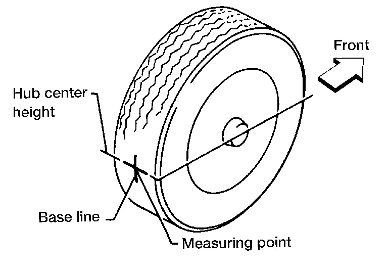
Put a mark on the base line of the tread (rear side) of both tires at the same height of hub center. These are measuring points.
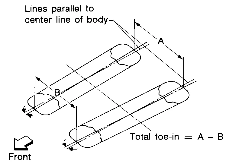
Measure the distance (A) from the rear side.
Push on the rear wheel to move the Nissan Murano vehicle slowly ahead and to rotate the wheels 180 degrees (1/2 turn).
CAUTION:
If the wheels have rotated more than 180 degrees (1/2 turn), try the above procedure again from the beginning. Do not push Nissan Murano vehicle backward.
Measure the distance (B) from the front side.
Use the formula below to calculate total toe-in.
| Total toe-in formula | : A - B |
| Total toe-in specification | : Refer to Wheel Alignment (Unladen). |
-
If the total toe-in is outside the specification, adjust the total toe-in. Refer to Adjustment.
TOE-IN ADJUSTMENT
-
Loosen the inner socket lock nut (A).
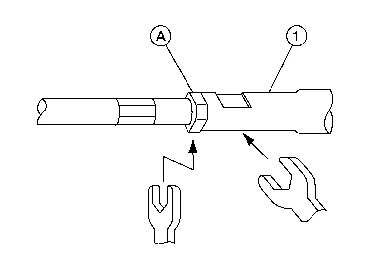
CAUTION:
To prevent damage, hold outer socket (1) across flats using suitable tool while loosening inner socket lock nut.
-
Adjust the toe using the inner socket.
CAUTION:
Always evenly adjust toe using LH and RH inner sockets alternately and adjust the total toe-in to the standard.
Total toe-in : Refer to Wheel Alignment (Unladen1). -
Tighten the inner socket lock nut. Refer to Exploded View.
CAUTION:
-
To prevent damage, hold outer socket across flats using suitable tool while tightening inner socket lock nut.
-
Inspect to make sure no boot deformation has occurred during toe-in adjustment. Adjust boot as necessary.
-
-
After toe-in adjustment, adjust neutral position of steering angle sensor. Refer to Description.
 Front Suspension Assembly
Inspection
COMPONENT PARTCheck the front suspension for the following:
Check each component for looseness or play.
Inspect each component for abnormal wear or damage...

Other information:
Nissan Murano (Z52) 2015-2024 Service Manual: U0073 Communication Bus a Off
DTC Description DTC DETECTION LOGICTCM communication blockage lasts for 2 seconds or more when turning ON the ignition switch. (Communication not established.) DTC CONSULT screen terms (Trouble diagnosis content) DTC detection condition U0073 COMM BUS A OFF (Control Module Communication Bus A Off) Diagnosis condition When turning ON the ignition switch Signal CAN communication Threshold TCM communication blockage (Communication not established) Diagnosis delay time Last for 2 seconds or more POSSIBLE CAUSEHarness or connector (CAN communication line is error)FAIL-SAFE Selector shock is large Start is slow Acceleration is slow Lock-up is not performed DTC Confirmation Procedure PREPARATION BEFORE WORK If another “DTC CONFIRMATION PROCEDURE” occurs just before, turn ignition switch OFF and wait for at least 10 seconds, then perform the next test...
Nissan Murano (Z52) 2015-2024 Service Manual: Mirrors :: Dtc/circuit Diagnosis. Main Power Window and Door Mirror Switch
Component Inspection NOTE: If equipped with ADP, refer to Component Function Check (for select switch) or Component Function Check (for mirror switch). CHECK MIRROR SWITCH & SELECT SWITCH Ignition switch OFF. Disconnect door mirror remote control switch connector...
Categories
- Manuals Home
- Nissan Murano Owners Manual
- Nissan Murano Service Manual
- System malfunction
- Shift lock release
- Power Steering Fluid (PSF)
- New on site
- Most important about car
Unfastening the seat belts. Checking seat belt operation
Unfastening the seat belts

To unfasten the seat belt, press the button
on the buckle  . The seat belt
automatically
retracts.
. The seat belt
automatically
retracts.