Nissan Murano: Aluminum Repair / Welding (aluminum)
To repair a crack or a hole in a steel plate, welding is usually used. Either oxygen and acetylene gas welding, arc welding, or brazing is commonly used. For aluminum alloy panels, TIG or MIG welding, which use inert gases (argon gas) as a shield gas, are usually used. This is because aluminum alloy has the following special features.
-
Its melting temperature is lower than iron, however the specific heat and latent heat are higher. It also has good conductivity. For these reasons, a large amount of heat must be applied in a very short time.
-
The melting point of aluminum alloy oxidized film is 2,020°C (3,668°F). In order to remove this film, cleaning by argon welding (TIG welding, MIG welding) or flux treatment is required.
-
Not removing oxidized films results in incomplete fusion or blowholes.
-
Heat expansion and contraction is approximately twice that of iron, which allows for easy distortion by welding.
| Property | Aluminum alloy | Iron | Effect of welding |
|---|---|---|---|
| Melting temperature °C (°F) |
560 - 640 (1,040 - 1,184) |
600 × 2.5 (1,112 × 2.5) |
|
|
Heat conduction efficiency cal/cm/sec/°C (BTU in/m2/h/°F) |
0.28 (812.69) |
0.28 × 0.57 (812.69 × 0.57) |
Large amount of heat in a short time required for welding. |
| Modulus of elasticity kg/mm2 (lb/in2) |
7,000 (9,646,875) |
7,000 × 3 (9,646,875 × 3) |
Easily deformed and very fragile. |
|
Coefficient of linear expansion (10-6) |
23.8 | 23.8 × 0.5 | |
| Conductivity (%) | 30 | 30 × 0.52 | Large current flow is required when compared to iron. |
| Oxidized film | Al2 O3 | Fe2 O3 | The melting point of aluminum alloy oxidized film is 2,020°C (3,668°F). In order to remove this film, cleaning by argon welding or flux treatment is required. |
For a filler metal, TIG welding rods and MIG welding electrode wires are available. Use filler metal that is suitable to the parent metal.
| Parent metal | Filler metal |
|---|---|
| Front fender, hood: 5000 series, 6000 series | A5356 |
| Door: 6000 series | A5356 |
TIG is the abbreviation for tungsten inert gas shielded arc welding. TIG has the following special features.
Special features
-
Initial cost of the equipment is low, as is maintenance expense.
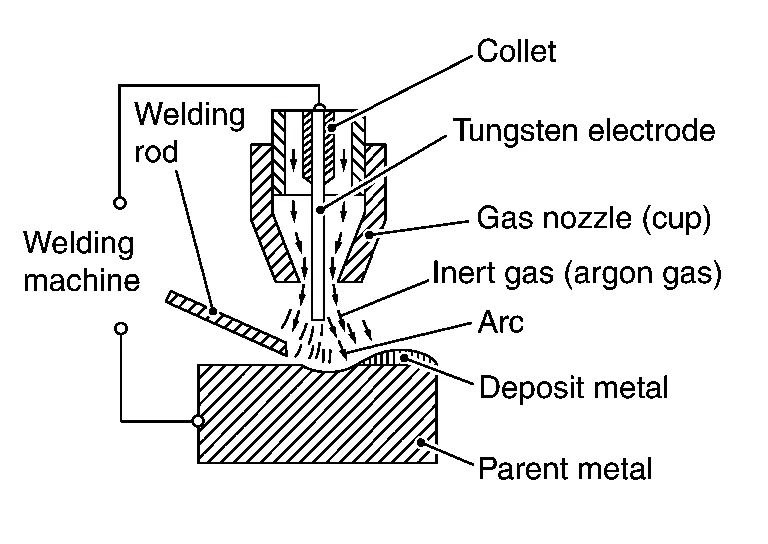
-
For ordinary electric power, high frequency alternating current is used.
-
Easy to learn in a short time.
-
Excellent strength and anti-corrosion properties.
-
Ideal for welding instruction and training.
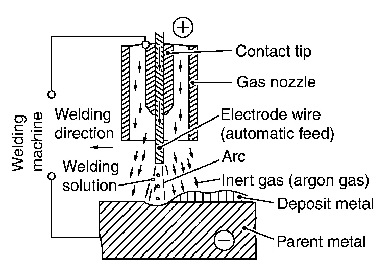
MIG is the abbreviation for metal inert gas shielded arc welding. MIG welding has the following special features.
(1) NORMAL MIG WELDING
MIG welding is the most commonly used welding method. As shown in the figure, a wire serving as an electrode is continuously fed into the welding area, and an arc is generated between the wire tip and the parent metal. Normally, an electrode wire measuring 1.2 mm - 1.4 mm (0.047 in - 0.055 in) in diameter, with an electrical current of 110 A - 360 A, is used for welding a plate having a thickness of 2 mm (0.079 in) or more.
(2) SHORT ARC MIG WELDING METHOD
When welding a thin plate, a short arc welding method is generally used.
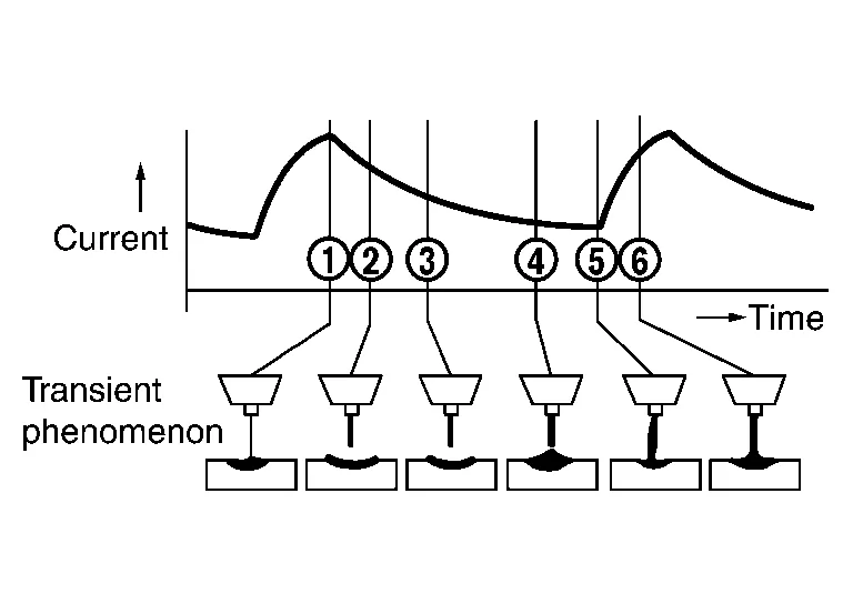
-
As shown in the figure, a short circuit and arc pattern is repeated.
-
When compared to ordinary MIG welding, using this short circuit transient method requires less heating, and therefore welding of a thin plate measuring 1 mm (0.04 in) in thickness can be accomplished.
-
The short arc welding conditions are shown below.
For the torch in the short arc welding, a thin wire measuring 0.8 mm - 1.2 mm (0.031 in - 0.047 in) in diameter and wound in a small spool is installed.
|
Plate thickness t = mm (in) | Shape of welding |
Current (A) |
Voltage (V) | Argon flow rate  (US gal, Imp gal)/min (US gal, Imp gal)/min | Welding speed mm (in)/min |
|---|---|---|---|---|---|
| 1 (0.04) |
|
45 | 12 | 13 (3-3/8, 2-7/8) | 600 (23.62) |
| 2 (0.08) | 85 | 15 | 15 (4, 3-1/4) | 600 (23.62) | |
| 3 (0.12) | 120 | 22 | 15 (4, 3-1/4) | 600 (23.62) |
(3) PULSED ARC WELDING METHOD
To enable spray transfer, even in the current range, which is equivalent to or lower than the critical current (spray transfer limiting current), pulse waveform is added to this welding method. Because this method allows stable penetration and bead shape while preventing heat gain, it is suitable for thin plate welding.
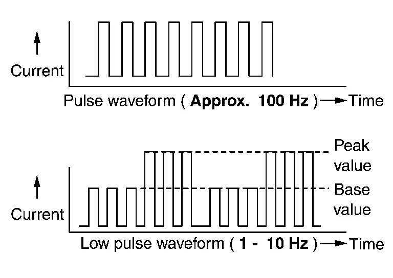
LOW PULSE FUNCTION
-
In addition to the pulse function, this function makes it easier to create imbricate bead shape.
-
It is effective in preventing burn through during the thin plate welding and the welding of panels with a gap present in between.
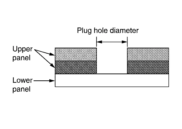
(1) PLUG WELDING
MIG plug welding method is used to repair the spot welded portions.
Keep the upper panel and lower panel tightly together. Before welding, contact closely the points to be plug welded.
Observe the welding condition described in the Body Repair Manual.
(a) Welding condition (plug welding)
Basically, the following welding conditions are intended for horizontal welding. Therefore, depending on the welding direction, adjustment may be necessary.
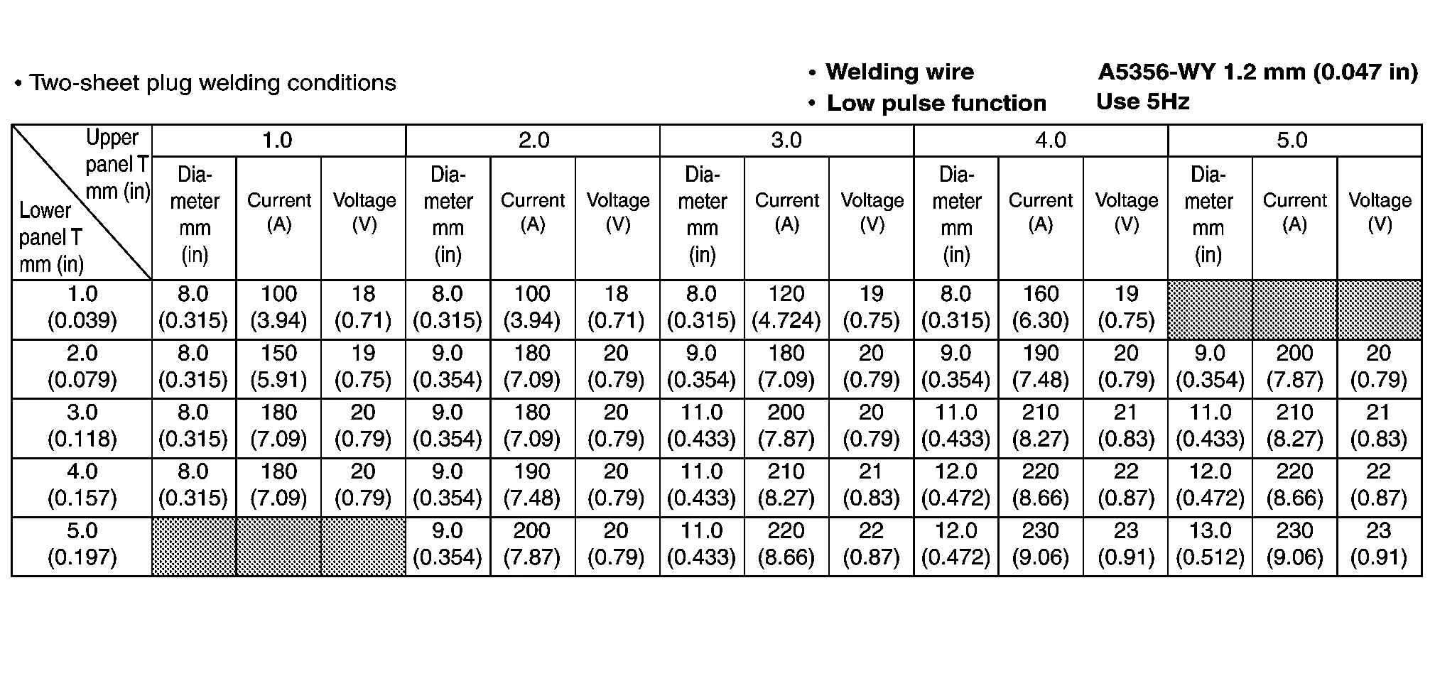
(b) Three-sheet plug welding condition
Consider the total thickness of two upper panels as the upper panel thickness. Using this thickness, apply the two-sheet plug welding conditions to set plug hole diameter, current, and voltage.
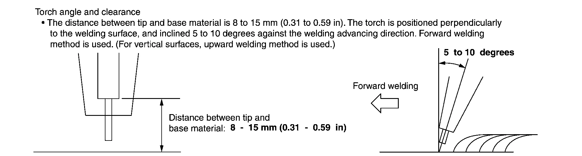
(c) Torch movement
-
Thickness of lower panel
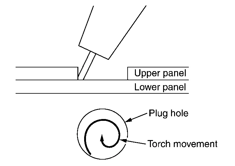
1.4 mm (0.055 in) or less Weld from the plug hole circumference toward the center in a circular motion.
-
Thickness of lower panel
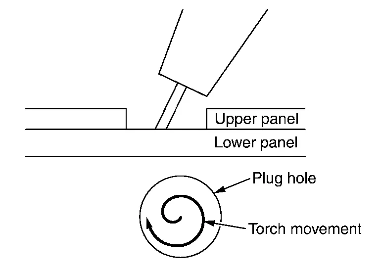
1.5 mm (0.059 in) or more Weld from the plug hole center toward the circumference in a circular motion.
(d) Backing block
When thin panels are plug welded, a backing block, as shown in the figure, is placed on the underside of the panels, and fixed onto the plug hole side with a clamp.
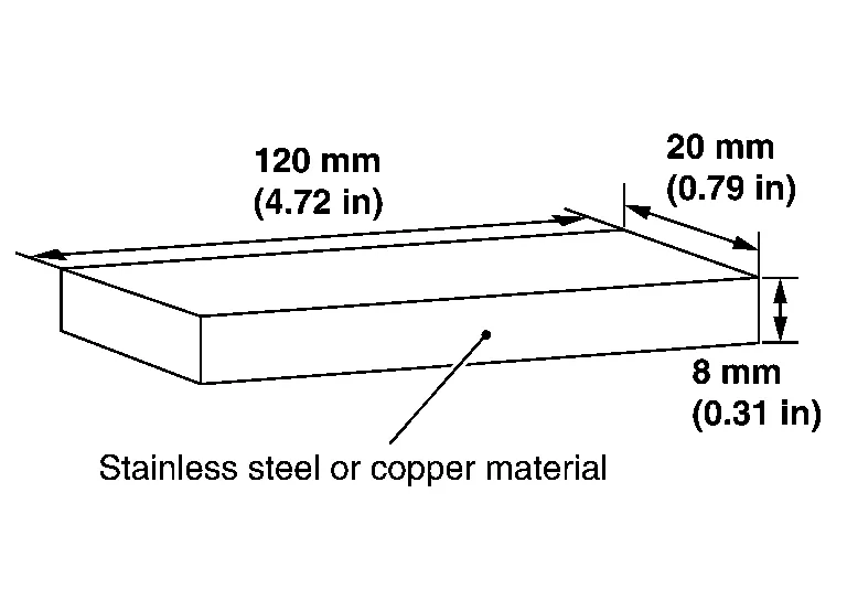
This is to prevent thin panels from burning through.
For locations where backing strips cannot be applied, be careful not to burn through.
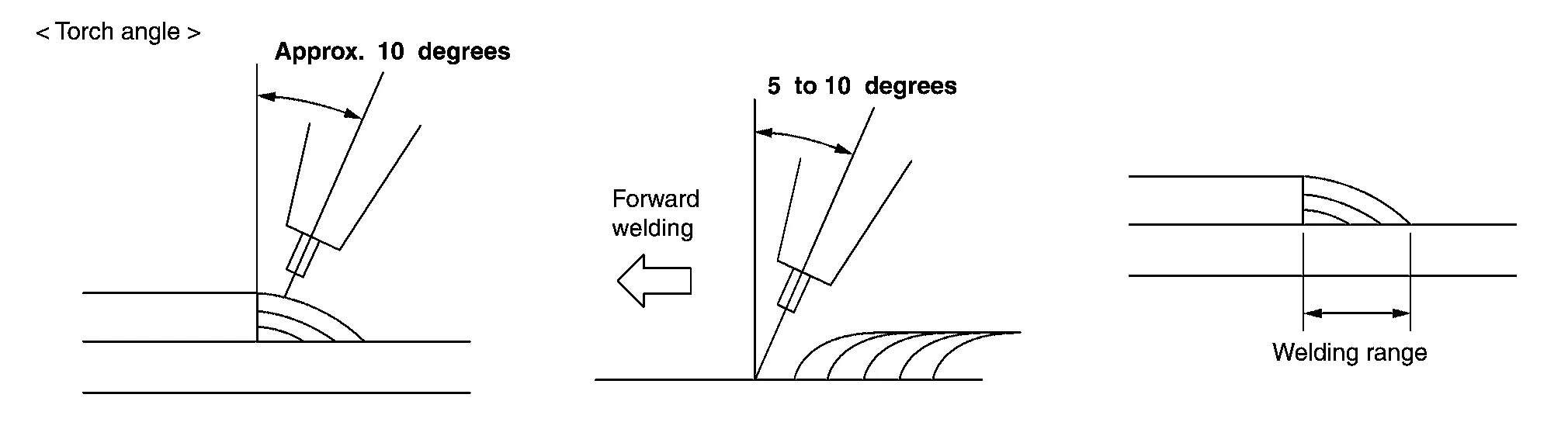
(2) FILLET WELDING
-
Before welding, contact closely the points to be fillet welded.
-
Observe the welding conditions and lengths specified in the Body Repair Manual.
-
Set the welding range for the fillet welding cross section so that it is same as the panel thickness or wider. When the panels have different thicknesses, perform welding according to the welding conditions applicable to the thinner panel.
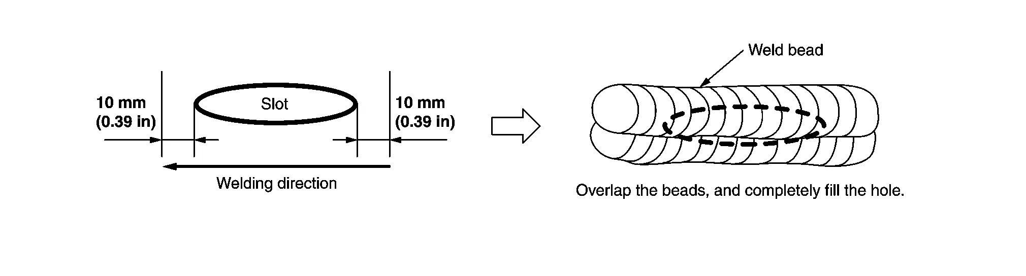
(3) SLOT WELDING
-
Before welding, contact closely the points to be slot welded.
-
Observe the welding conditions specified in the Body Repair Manual.
-
Welding range is from 10 mm (0.39 in) before the slot to 10 mm (0.39 in) after the slot.
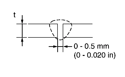
(4) BUTT WELDING
Observe the welding conditions specified in the parts replacement procedure.
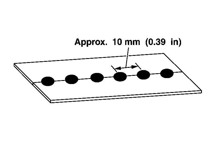
-
Tack welding: Temporarily, but securely weld at approximately 10 mm (0.39 in) intervals.
-
Remove aluminum oxides and magnesium oxides generated at tack welded points. Not doing so results in a welding malfunction.
-
Regular welding.
-
Wear long sleeved work uniform, work cap, and safety shoes. Wear safety goggles, gloves, earplugs, and dustproof respirator if necessary.
-
MIG arc welding for aluminum plates emits sparks. Do not stare directly at them. Before working, be sure to wear protectors to avoid getting burned.
-
Always perform pre-treatment of the parent metal.
Dirt and oxidization film on the parent metal will cause defective welding. The following pre-treatment should be performed prior to welding. Oil film should be cleaned using Silicon Off or white gasoline.
Surface should then be polished using a thin wire stainless steel brush.
Oxide film is reproduced in approximately 30 minutes to 1 hour.
Therefore, it is best to perform the pre-treatment immediately before welding.
Even if pre-treatment for various locations has already been performed, it is necessary to use a wire brush again immediately before welding.
-
Use filler metal (welding rod or welding wire) that is suitable for the parent metal.
-
Filler metal used for aluminum welding flows easier than for steel welding, and therefore the welding surface should be in the horizontal position.
-
For TIG and MIG welding, even a 0.5 m/s (1.6 ft/s) breeze will greatly effect the seal. When performing welding outside, select a place where dust and moisture are minimized. A shelter should be constructed for protection from wind or rain.
-
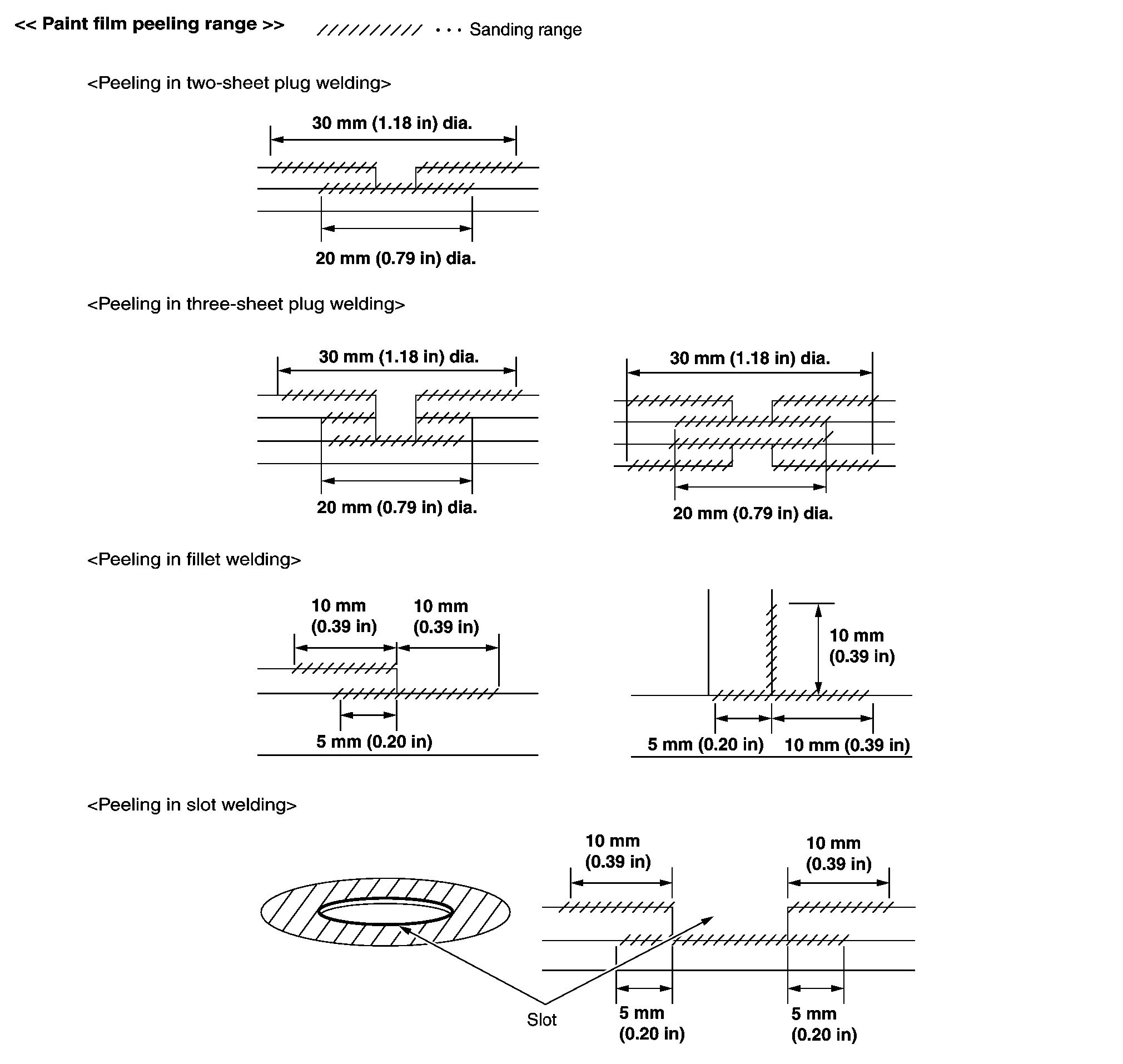
Remove paint film of the welding portions and electrodeposition coating of the service parts using a disc sander.
When removing, be careful not to excessively sand aluminum alloy base material.
 Sheet Metal Work (aluminum)
Sheet Metal Work (Aluminum)
Repairing aluminum alloy panels is basically the same as repairing steel panels. Special considerations for repairing aluminum alloy are listed below...
 Body Straightening (aluminum)
Securing the Vehicle
When fixing the aluminum body to the body straightening equipment, set an aluminum alloy retaining plate [thickness: approximately 5 mm (0...
Other information:
Nissan Murano (Z52) 2015-2024 Service Manual: C1a23 Unit Low Temp
DTC Description DTC DETECTION LOGIC DTC Trouble diagnosis name DTC detecting condition C1A23 (97) UNIT LOW TEMP Temperature detected by the temperature sensor integrated in distance sensor (ICC sensor) remains less than -40 °C for 5 seconds or more POSSIBLE CAUSETemperature around the distance sensor (ICC sensor) becomes extremely lowFAIL-SAFEThe following systems are canceled...
Nissan Murano (Z52) 2015-2024 Service Manual: Component Parts. Automatic Emergency Braking System
Component Parts Location A. Center of windshield behind the auto anti-dazzling inside mirror B. Center of instrument panel (view with center console removed) C. Engine room right side D. Front bumper (center) E. Engine room left side F...
Categories
- Manuals Home
- Nissan Murano Owners Manual
- Nissan Murano Service Manual
- Jacking up vehicle and removing the damaged tire
- System malfunction
- High Beam Assist (if so equipped)
- New on site
- Most important about car
Driver and passenger supplemental knee air bag

Driver’s side
The knee air bag is located in the knee bolster, on the driver’s and passenger’s side. All of the information, cautions and warnings in this manual apply and must be followed. The knee air bag is designed to inflate in higher severity frontal collisions, although it may inflate if the forces in another type of collision are similar to those of a higher severity frontal impact. It may not inflate in certain collisions.

Passenger’s side